


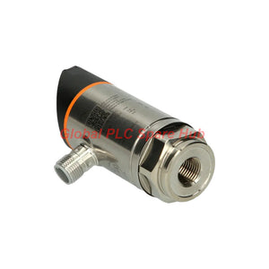
PN3094 ifm Pressure Sensor with Display | Smart IO-Link Process Monitoring
Manufacturer: IFM
Product No.: PN3094
Condition: In stock
Product Type: Pressure Sensor
Product Origin: USA
Payment: T/T, Western Union
Weight: 300g
Shipping port: Xiamen
Warranty: 12 months
Estimate delivery times: 12-26 days (International), 3-6 days (United States).
Return within 30 days of purchase. Duties & taxes are non-refundable.
Guaranteed Safe Checkout
PN3094 ifm PN Series Electronic Pressure Sensor with Display
The ifm PN3094 is an electronic pressure sensor with a red/green display and a ceramic-capacitive measuring cell for liquid and gas applications. Its −1 to 10 bar relative-pressure range supports pressure and vacuum monitoring in industrial equipment.
The sensor combines local pressure indication, a configurable PNP switching output, an analog output, and an integrated IO-Link interface. Engineers can use these functions for local threshold monitoring, controller-based process feedback, and digital parameter access through a compatible IO-Link master.
Ordering reference: PN3094
Associated order code supplied: PN-010-RER14-MFRKG/US/ /V
Product family: ifm PN pressure sensor with display
01 | Instrument Profile — Measurement, Switching, Communication
| Function | Specification | Engineering Significance |
|---|---|---|
| Measuring principle | Ceramic-capacitive measuring cell | Provides pressure measurement for compatible liquid and gas media. |
| Measuring range | −1 to 10 bar; −0.1 to 1 MPa; approximately −14.5 to 145 psi | Covers vacuum and positive relative-pressure monitoring within the specified range. |
| Pressure reference | Relative pressure and vacuum | Confirm that the application requires gauge pressure rather than absolute pressure. |
| Process media | Liquids and gases | Verify compatibility with the medium, wetted materials, and process temperature. |
| Display | Four-digit red/green alphanumeric display, green LED bar, yellow switching-status LED | Supports local reading of process values and visual identification of switching status. |
| Switching output | 1 × PNP, NO/NC parameterizable | Supports threshold-based control or alarm signaling when connected to compatible inputs. |
| Analog output | 4–20 mA or 0–10 V, according to configuration | Provides a process-value signal for compatible PLC analog inputs or control equipment. |
| Digital communication | IO-Link 1.1; SIO mode supported | Enables digital parameter access and process-data exchange with a compatible IO-Link master. |
| Process connection | G 1/4 internal thread, M6 I as specified | Check the mating interface and the exact connection drawing before installation. |
| Electrical connection | 1 × M12 A-coded, 4-pin connector with gold-plated contacts | Confirm pin assignment, cable compatibility, and the intended output mode. |
02 | Pressure Range and Mechanical Limits
| Parameter | Published Value | Selection Guidance |
|---|---|---|
| Measuring range | −1 to 10 bar | Select a range that covers normal operation and expected process transients. |
| Pressure rating | 75 bar (7.5 MPa) | Confirm the pressure rating against the process connection and system design. |
| Minimum burst pressure | 150 bar (15 MPa) | This is a burst limit, not an allowable operating pressure. |
| Vacuum resistance | −1000 mbar | Check the expected vacuum level and transient conditions. |
| Recommended tightening torque | 25–35 Nm | Follow the manufacturer's connection and installation instructions. |
| Housing diameter | 34 mm | Allow clearance for installation and visibility of the display. |
| Overall length | 90.7 mm | Check the available space around the process port and connector. |
| Weight | 235.5 g | Consider mounting support where vibration or mechanical loading is present. |
Pressure-selection note: The measuring range, rated pressure, and burst pressure describe different limits. Normal operation must remain within the applicable operating limits, even though the stated burst pressure is much higher.
03 | Output Signal Architecture
The sensor offers local indication, switching control, and analog or digital communication paths. Select the signal path according to the controller hardware and the process-control objective.
| Signal Path | Specified Capability | Typical Use |
|---|---|---|
| Local display | Four-digit red/green display with LED indicators | On-site pressure checks during commissioning and maintenance. |
| PNP switching output | One output, NO/NC parameterizable | Pressure threshold indication, interlocking, or alarm input to a compatible controller. |
| 4–20 mA analog signal | 0 bar = 4 mA; 10 bar = 20 mA; maximum load 500 Ω | Continuous pressure feedback to a compatible analog input. |
| 0–10 V analog signal | Minimum load resistance 2000 Ω | Voltage-based process feedback where the receiving input supports the signal range. |
| IO-Link | Revision 1.1, COM2 at 38.4 kBaud; SIO mode supported | Digital process-data exchange and parameter management through a compatible master. |
The listed analog alternatives should not be interpreted as proof that 4–20 mA and 0–10 V are available simultaneously. Confirm the selected output configuration and wiring requirements in the applicable ifm documentation.
04 | Control Settings and Measurement Performance
| Parameter | Specification | Practical Implication |
|---|---|---|
| Switch point SP | −0.9 to 10 bar | Sets the threshold for the selected switching function. |
| Reset point rP | −0.95 to 9.95 bar | Defines the return threshold and helps establish switching hysteresis. |
| Minimum SP/rP difference | 0.05 bar | Provides a minimum separation between switching and reset thresholds in the standard setting. |
| Setting increment | 0.05 bar in CMPT=2; 0.01 bar in CMPT=3 high-resolution mode | Check the configured mode before planning fine threshold adjustments. |
| Switch point accuracy | Less than ±0.5% of span | Relevant when defining alarm margins around the process limit. |
| Repeatability | Less than 0.1% of span | Supports evaluation of consistency across repeated pressure cycles. |
| Characteristic deviation | Less than ±0.25% BFSL | Use the stated linearity-related specification when reviewing measurement performance. |
| Long-term stability | Less than ±0.05% of span per 6 months | Consider the specified stability when planning verification intervals. |
| Response time | Less than 3 ms | Suitable for fast pressure changes within the sensor's operating limits and configuration. |
| Switch-on delay | Less than 0.3 s | Allow for startup before evaluating the process reading or output state. |
| Programmable delay | dS/dr: 0–50 s | Can help suppress unwanted switching caused by brief process fluctuations. |
| Process-value damping | 0–4 s | Adjust only as needed; excessive damping can obscure rapid pressure changes. |
05 | IO-Link and Electrical Integration
- Supply voltage: 18–30 V DC, nominal, supplied from a SELV/PELV-compliant source.
- Current consumption: Typically less than 35 mA.
- Communication: IO-Link revision 1.1, COM2 at 38.4 kBaud, with SIO mode supported.
- Master interface: Type A IO-Link master port, as specified.
- Device ID: 431 for CMPT=2; 615 for CMPT=3 high-resolution mode.
- Minimum process cycle: 2.3 ms; 3 ms in CMPT=3 mode, according to the supplied specifications.
- Digital output voltage drop: Maximum 2.5 V DC.
- Switching frequency: Less than 170 Hz.
- Protection features: Reverse-polarity protection and integrated watchdog.
- Insulation resistance: Minimum 100 MΩ at 500 V DC.
- Protection class: III.
When using IO-Link, verify the master port configuration, device identification, process-data mapping, and parameterization method. The sensor has an integrated IO-Link interface; no separate communication expansion is specified.
06 | Materials and Operating Environment
| Item | Specification | Engineering Check |
|---|---|---|
| Housing materials | Stainless steel 316L/1.4404, PBT+PC-GF30, PBT-GF20, PC | Review the complete assembly material list against the installation environment. |
| Wetted materials | 316L stainless steel, Al2O3 ceramic, FKM | Confirm compatibility with the process medium and cleaning chemicals. |
| Operating temperature | −25°C to 80°C for ambient and medium, as supplied | Keep both ambient and medium conditions within the applicable limits. |
| Storage temperature | −40°C to 100°C | Observe storage conditions before installation. |
| Ingress protection | IP65 and IP67 | Confirm that the connector, mating cable, and installation preserve the required protection. |
| Shock resistance | 50 g, 11 ms, DIN EN 60068-2-27 | Consider shock exposure during machinery operation and installation. |
| Vibration resistance | 20 g, 10–2000 Hz, DIN EN 60068-2-6 | Verify that mounting and cable support suit the actual vibration environment. |
| Relative humidity | No specific %RH value listed in the supplied technical data | Consult the manufacturer's documentation if a defined humidity limit is required. |
07 | Application Fit — Equipment and Process Scenarios
| Equipment | Potential Application | Selection Considerations |
|---|---|---|
| Pump skids | Monitoring suction or discharge pressure within the sensor's range | Check pressure transients, process connection, medium compatibility, and output type. |
| Hydraulic auxiliary circuits | Pressure feedback and threshold monitoring in compatible low-range applications | Confirm the maximum normal and transient pressure remains within the rated limits. |
| Pneumatic systems | Monitoring vacuum or positive relative pressure | Verify pressure range, switching thresholds, and response requirements. |
| Liquid handling equipment | Pressure monitoring in compatible process lines | Check fluid compatibility with 316L, ceramic, and FKM wetted materials. |
| Industrial filling and dosing equipment | Pressure threshold detection and process feedback | Evaluate dynamic pressure changes and set appropriate switching delays. |
| Automated test benches | Local pressure indication and controller-based monitoring | Confirm accuracy requirements, calibration practices, and signal interface. |
| PLC and IO-Link installations | Digital pressure data and configurable sensor parameters | Confirm master compatibility, device ID, process-data mapping, and required analog or SIO operation. |
These scenarios describe potential uses based on the supplied measurement range and interfaces. Final suitability depends on actual pressure transients, process media, control-system compatibility, and installation conditions.
08 | Commissioning and Field Diagnostic Matrix
| Symptom | Possible Cause | Recommended Diagnostic Action |
|---|---|---|
| Display remains blank | Supply voltage absent, incorrect wiring, connector issue, or sensor fault | Measure supply voltage at the connector, verify pin assignment, inspect the mating cable, and check startup behavior. |
| Displayed pressure differs from the reference gauge | Different pressure reference, incorrect range interpretation, process pulsation, or measurement offset | Confirm both devices measure the same pressure reference. Compare readings under stable conditions and follow the manufacturer's verification procedure. |
| PNP output does not change state | SP/rP settings, NO/NC configuration, wiring, load, or output mode mismatch | Review switching thresholds and output configuration. Check the receiving input and verify the output circuit against the wiring diagram. |
| PLC analog value is incorrect | Incorrect output selection, input scaling, common reference, or excessive load | Confirm whether the sensor uses 4–20 mA or 0–10 V. Verify PLC channel settings, scaling, wiring, and load limits. |
| IO-Link master does not identify the sensor | Port mode, pin wiring, master compatibility, or device configuration issue | Check the master port settings, A-coded 4-pin connection, IO-Link revision support, and expected Device ID for the configured CMPT mode. |
| Output switches repeatedly near a threshold | Insufficient hysteresis, pressure pulsation, or unsuitable delay settings | Review SP and rP separation, examine the process trend, and adjust delay only when consistent with the process response requirements. |
| Pressure response appears slow | Configured damping, process-line restrictions, pressure pulsation, or upstream system behavior | Review the damping setting and compare the sensor reading with an independent reference under controlled conditions. |
| Reading drifts over time | Temperature changes, process conditions, installation stress, or sensor performance drift | Record readings against a suitable reference, check operating temperature, and follow the recommended calibration or verification procedure. |
Diagnostic note: Distinguish sensor measurement problems from signal transmission and PLC scaling problems. Check the local display first, then compare the configured output, electrical signal, and controller reading to isolate the fault.
09 | Global PLC Spare HUB's Insight
The ifm PN3094 combines a local display with switching, analog, and IO-Link interfaces. For engineers, the main selection decision is how the pressure value will be used: a local indication, a discrete threshold, a continuous PLC input, or digital process data.
- For PLC retrofits: Confirm whether the existing input expects PNP switching, 4–20 mA, 0–10 V, or IO-Link. Check the exact configured output before changing wiring.
- For pressure and vacuum applications: Confirm that the negative-pressure range meets the actual process requirement and that the system uses relative pressure rather than absolute pressure.
- For process compatibility: Review the wetted materials, including 316L stainless steel, Al2O3 ceramic, and FKM, against the medium and cleaning conditions.
- For threshold stability: Choose SP/rP settings based on normal process variation. Use delays and damping carefully so that noise is reduced without masking a meaningful pressure event.
- For digital integration: Verify the IO-Link master, Device ID, process-data mapping, and CMPT configuration before commissioning.
This selection guidance is based on the supplied specifications. Confirm the exact order code and configured signal options against the applicable ifm documentation before replacing or commissioning the device.
10 | Global PLC Spare HUB Review
The PN3094 is a pressure-monitoring option for applications requiring a readable local display and multiple control-system interface choices. Its ceramic-capacitive measuring cell, −1 to 10 bar range, parameterizable PNP output, and IO-Link 1.1 interface support several common industrial monitoring architectures.
Before ordering, verify the process connection, wetted-material compatibility, selected analog output, switching configuration, and IO-Link master requirements. For replacement projects, comparing the complete order code and wiring arrangement helps reduce commissioning errors.
11 | Warranty and Shipping
- Warranty: 12-month warranty, subject to the applicable seller warranty terms.
- Shipping options: FedEx, UPS, and DHL, subject to destination and service availability.
- Order verification: Provide the PN3094 model, complete order code, required quantity, and target equipment details for compatibility review.
- Quotation support: Contact Global PLC Spare HUB for current pricing, availability, and order information.
12 | Frequently Asked Questions
Q1: Should I select IO-Link or a conventional analog signal for a PN3094 installation?
A: Choose according to the receiving controller and maintenance requirements. A 4–20 mA or 0–10 V output suits compatible analog inputs, while IO-Link supports digital process-data exchange and parameter access through a compatible master. Confirm the configured output and required PLC hardware before ordering.
Q2: Why can two pressure instruments show different values when connected to the same process?
A: Check whether both instruments measure relative or absolute pressure, and compare their ranges, response settings, installation points, and calibration status. Pressure pulsation or a restricted impulse path can also cause differences. Compare readings under stable conditions before changing the sensor settings.
Q3: How should I set SP and rP to prevent unnecessary switching?
A: Base the switch and reset thresholds on the normal operating range and the process's expected fluctuations. Maintain the specified minimum SP/rP separation, then assess whether a delay is appropriate. Do not add excessive damping or delay where a rapid pressure event requires a timely response.
Q4: What should I verify before installing this sensor in a liquid line?
A: Confirm the operating and transient pressure, the G 1/4 connection, recommended tightening torque, process temperature, and compatibility of the medium with 316L stainless steel, Al2O3 ceramic, and FKM. Check that the installation does not exceed the rated pressure and that the connector maintains the required ingress protection.
Q5: What information should I provide to confirm the correct PN3094 replacement?
A: Provide the model and full order code, the existing output type, supply voltage, process connection, pressure range, and PLC or IO-Link master details. If the current unit has failed, include its displayed value, output behavior, and any controller diagnostic information. This helps distinguish a model mismatch from a wiring or configuration issue.
Request a Quote for PN3094
Looking for the ifm PN3094 pressure sensor with display? Contact Global PLC Spare HUB with the complete order code, quantity, and application details to request pricing, availability, and compatibility support.

Tags
Q: Are these parts 100% original and new?
A: Yes. Every component is guaranteed to be 100% original, brand-new, and factory-sealed. We also provide a 12-month comprehensive warranty for your peace of mind.
Q: How fast is the shipping to my country?
A: For in-stock items, we offer same-day dispatch. International express shipping (DHL/FedEx/UPS) typically delivers within 3–5 business days worldwide.
Q: Can I get a formal quotation with shipping costs?
A: Absolutely. Our sales team is ready to provide a detailed Proforma Invoice (PI) including the most competitive shipping rates for your location.
Q: Do you offer discounts for bulk orders?
A: We provide volume-based pricing for large projects or multiple-item orders. Please contact us to get our Best Price Guarantee.
12-Month Comprehensive Warranty
Every part supplied by Global PLC Spare Hub is covered by a 12-month warranty from the date of invoice.
- Coverage: Functional defects and hardware failures under normal operating conditions.
- Commitment: We provide immediate repair, replacement, or a full refund for any verified defective components to minimize your operational downtime.
Returns & Exchange Policy
We offer a 30-day return policy to ensure you receive the exact part your system requires.
- Eligibility: Returns are accepted for uninstalled items in their original, factory-sealed packaging.
- RMA Process: Please contact our support team to obtain a Return Merchandise Authorization (RMA) number before shipping.
- Fast Processing: Refunds or exchanges are processed within 3–5 business days after the returned item passes our technical inspection.
Need Technical Assistance?Not sure if this part is compatible with your system? [Consult our Engineers] before purchasing to ensure 100% compatibility.
People Also Bought


