


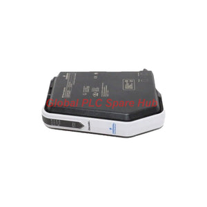
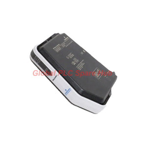
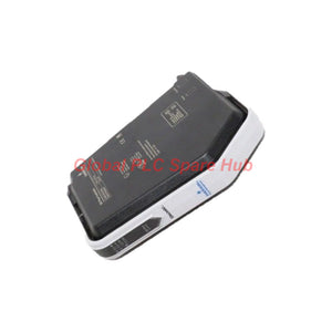
KJ3208X1-BK1 Emerson Digital Output Module | 24 VDC Isolated 8-Channel
Manufacturer: Emerson
Product No.: KJ3208X1-BK1
Condition: In stock
Product Type: Digital Output Module
Product Origin: USA
Payment: T/T, Western Union
Weight: 500g
Shipping port: Xiamen
Warranty: 12 months
Estimate delivery times: 12-26 days (International), 3-6 days (United States).
Return within 30 days of purchase. Duties & taxes are non-refundable.
Guaranteed Safe Checkout
KJ3208X1-BK1 | Emerson 8-Channel 24 VDC Isolated Digital Output Module
The Emerson KJ3208X1-BK1 is an eight-channel digital output module designed for compatible industrial control systems. It provides isolated 24 VDC output control for field circuits and supports applications that require reliable switching between controller logic and external devices.
The module combines local-bus power requirements, channel-level field-circuit specifications, and defined environmental operating limits. Its B5 terminal-block key position also makes hardware matching an important part of replacement planning.
- Manufacturer: Emerson
- Model: KJ3208X1-BK1
- Product type: 8-channel isolated digital output module
- Output class: 24 VDC
- Terminal block key position: B5
- Maintenance: No user-serviceable parts; calibration is not required.
01 | Output Architecture and Power Budget
When integrating this module, distinguish the local-bus supply from the field-circuit rating. These values describe different parts of the system and should not be treated as interchangeable power limits.
| Parameter | Specified Value | Engineering Interpretation |
|---|---|---|
| Output channels | 8 | Supports eight discrete output points. |
| Output class | 24 VDC | Confirm field-device voltage and output wiring requirements. |
| Local-bus power | 12 VDC at 150 mA | Account for module power requirements in the local-bus design. |
| Field-circuit specification | 60 VDC at 1 A per channel | Verify the applicable output limits and load compatibility in the manufacturer's manual. |
| Isolation | Isolated digital output | Follow the manufacturer's isolation and wiring specifications. |
Load-selection note: The stated 60 VDC and 1 A per channel figures should not be interpreted as a guarantee that every load can operate at those values simultaneously. Confirm output derating, load type, total field power, and switching limits in the module documentation.
02 | Environmental Qualification Matrix
| Environmental Parameter | Specification | Installation Consideration |
|---|---|---|
| Ambient temperature | −40°C to +70°C | Keep the installed module within the specified operating range. |
| Relative humidity | 5–95%, non-condensing | Prevent condensation inside the control enclosure. |
| Ingress protection | IP20 | Install inside a suitable enclosure with appropriate access protection. |
| Shock | 10 g, half-sine wave, 11 ms | Review mechanical conditions against the specified shock profile. |
| Vibration, low-frequency range | 1 mm peak-to-peak from 2 to 13.2 Hz | Check cabinet mounting and vibration exposure. |
| Vibration, higher-frequency range | 0.7 g from 13.2 to 150 Hz | Confirm that the installation remains within the stated limits. |
| Airborne contaminants | ISA-S71.04-1985, Class G3 | Assess corrosive contaminants and enclosure protection. |
The IP20 rating does not provide protection against water ingress. Select the control cabinet and environmental controls according to the actual installation conditions.
03 | Terminal Block Matching — B5 Key Position
The KJ3208X1-BK1 specifies terminal-block key position B5. Its rotary keying system helps prevent incompatible I/O cards and terminal blocks from being paired after the keys are correctly configured.
- Verify the module model before selecting a replacement terminal block.
- Check that the terminal block's rotary key matches the required B5 position.
- Inspect the connector interface and terminal-block condition before installation.
- Confirm the field wiring and any fused terminal-block requirements against the approved wiring diagram.
- Do not force a mismatched module and terminal block together.
Keying helps prevent incorrect hardware combinations, but it does not replace verification of the terminal assignment, field wiring, or electrical ratings.
04 | Hazardous-Area Installation and Removal Safety
The supplied hazardous-atmosphere information lists the following marking and certification identifiers. Confirm their applicability to the exact module, installation location, and current site requirements before use.
| Item | Supplied Information |
|---|---|
| Hazardous-atmosphere marking | II 3G Ex nA IIC Gc |
| ATEX certificate reference | FM12ATEX0090U |
| IECEx certificate reference | IECEx FMG 12.0035U |
Removal and insertion precautions:
- Do not remove or insert the module with system power energized unless the area is known to be non-hazardous.
- Only one unit may be removed or inserted at a time under the stated exception.
- De-energize non-sparking field circuits before removal or insertion.
- Include the fused terminal block when isolating the relevant field circuits.
- Follow site lockout procedures and the manufacturer's installation instructions.
Never rely on the module's hazardous-area marking alone to determine whether live work is permitted. The complete installation, protection concept, and site procedures must support the intended activity.
05 | Compatible Equipment and Application Scenarios
This module suits discrete control tasks where a compatible automation system must switch external field loads through isolated digital output channels.
- Process-control panels: Switch compatible discrete field devices from a supported controller output system.
- Valve solenoid circuits: Control compatible DC solenoid loads after checking inrush current and output ratings.
- Relay interface circuits: Drive suitable interface relays where the coil voltage and current meet the module's limits.
- Machine permissive signals: Provide discrete commands to compatible field circuits within an approved control design.
- Industrial plant I/O cabinets: Support output-point replacement when the existing hardware, terminal block, and system configuration match.
Do not assume universal compatibility with all Emerson controllers or I/O carriers. Confirm the supported hardware family, firmware requirements, terminal-block pairing, and system configuration before ordering.
06 | Field Diagnostics — From Output Command to Field Load
When a field device does not respond, trace the signal path from the controller command to the physical load. Separate logic, module, wiring, and load-related faults before replacing hardware.
| Observed Symptom | Diagnostic Checks | Purpose |
|---|---|---|
| Field device does not energize | Verify the controller command, field supply, terminal assignment, and load wiring. | Identify missing commands or field-power problems. |
| Output state differs from the controller command | Check channel mapping, logic configuration, and the applicable module diagnostics. | Separate configuration issues from hardware faults. |
| Output drops out under load | Measure the field supply and review load current, inrush, and output limits. | Identify overload or supply instability. |
| Repeated output-channel faults | Inspect wiring shorts, load condition, terminal connections, and field-circuit protection. | Find external conditions that may stress the output. |
| Module cannot be installed correctly | Verify module identity, terminal-block key position, and connector alignment. | Prevent incompatible hardware pairing or connector damage. |
| Intermittent operation in the cabinet | Review terminal tightness, vibration exposure, temperature, humidity, and contamination. | Identify environmental or connection-related causes. |
Use approved diagnostic tools and plant procedures when checking live circuits. Isolate power before inspecting or changing field wiring whenever the operating procedure requires it.
07 | Global PLC Spare HUB's Insight
For digital output troubleshooting, the most useful first step is to compare the commanded state with the measured field-circuit condition. A correct PLC command does not prove that the output wiring, field supply, or connected load is healthy.
When a channel repeatedly fails, inspect the load before installing a replacement module. A shorted cable, damaged solenoid, or excessive inrush current can cause the same symptom to return after hardware replacement.
Terminal-block compatibility deserves equal attention during maintenance. The B5 key position helps identify the intended pairing, but technicians should still verify the complete module and terminal-block part numbers before installation.
For hazardous-area work, plan isolation before removing hardware. The supplied instructions specifically address energized insertion and removal, non-sparking field circuits, and fused terminal blocks. Following these requirements reduces avoidable maintenance and safety risks.
08 | Maintenance and Service Requirements
- User servicing: The module contains no user-serviceable parts and should not be disassembled.
- Calibration: Calibration is not required.
- Inspection: Check connectors, terminal-block keying, field wiring, and visible signs of damage.
- Environmental review: Confirm enclosure conditions, temperature, humidity, and contaminant exposure.
- Replacement verification: Confirm model, terminal-block compatibility, wiring, and system configuration before returning equipment to service.
09 | Product Supply, Warranty and Shipping
- Manufacturer: Emerson
- Part number: KJ3208X1-BK1
- Product type: Eight-channel 24 VDC isolated digital output module
- Terminal-block key position: B5
- Warranty: 12 months, subject to the seller's written warranty terms.
- Shipping methods: FedEx, UPS, and DHL, subject to destination and shipping arrangements.
- Packaging and included accessories: Confirm the exact supplied contents before purchase.
- Compatibility verification: Provide the controller or I/O system model and terminal-block part number when requesting a quotation.
10 | Frequently Asked Questions
Q1: What information should be checked before replacing this module during a planned shutdown?
A: Record the module model, terminal-block part number, B5 key position, field wiring, and controller configuration. Confirm the replacement matches the approved hardware list before the shutdown begins.
Q2: How should I evaluate whether a solenoid load is suitable for the output channel?
A: Check nominal voltage, steady-state current, inrush current, and the load's inductive characteristics. Compare these values with the manufacturer's output limits and any required interposing relay or suppression arrangement.
Q3: Can the module be calibrated to correct a field output problem?
A: Calibration is not required according to the supplied information. Investigate output configuration, field power, wiring, load condition, and module diagnostics instead of attempting internal adjustment.
Q4: What should a maintenance team do if the replacement fits mechanically but does not operate?
A: Verify the exact module identity, terminal-block keying, field wiring, system compatibility, and controller configuration. Mechanical fit alone does not establish electrical or functional compatibility.
Q5: What documents should buyers request for hazardous-area replacement planning?
A: Request the applicable installation manual, current certification documentation, terminal-block requirements, and wiring instructions. Confirm that the exact hardware and complete installation meet the site's hazardous-area requirements.
Request a Quote from Global PLC Spare HUB
Contact Global PLC Spare HUB for pricing, availability, and compatibility checks for the Emerson KJ3208X1-BK1. Include the host control system, terminal-block model, field-load requirements, and installation conditions to support accurate replacement planning.
Tags
Q: Are these parts 100% original and new?
A: Yes. Every component is guaranteed to be 100% original, brand-new, and factory-sealed. We also provide a 12-month comprehensive warranty for your peace of mind.
Q: How fast is the shipping to my country?
A: For in-stock items, we offer same-day dispatch. International express shipping (DHL/FedEx/UPS) typically delivers within 3–5 business days worldwide.
Q: Can I get a formal quotation with shipping costs?
A: Absolutely. Our sales team is ready to provide a detailed Proforma Invoice (PI) including the most competitive shipping rates for your location.
Q: Do you offer discounts for bulk orders?
A: We provide volume-based pricing for large projects or multiple-item orders. Please contact us to get our Best Price Guarantee.
12-Month Comprehensive Warranty
Every part supplied by Global PLC Spare Hub is covered by a 12-month warranty from the date of invoice.
- Coverage: Functional defects and hardware failures under normal operating conditions.
- Commitment: We provide immediate repair, replacement, or a full refund for any verified defective components to minimize your operational downtime.
Returns & Exchange Policy
We offer a 30-day return policy to ensure you receive the exact part your system requires.
- Eligibility: Returns are accepted for uninstalled items in their original, factory-sealed packaging.
- RMA Process: Please contact our support team to obtain a Return Merchandise Authorization (RMA) number before shipping.
- Fast Processing: Refunds or exchanges are processed within 3–5 business days after the returned item passes our technical inspection.
Need Technical Assistance?Not sure if this part is compatible with your system? [Consult our Engineers] before purchasing to ensure 100% compatibility.
People Also Bought


