


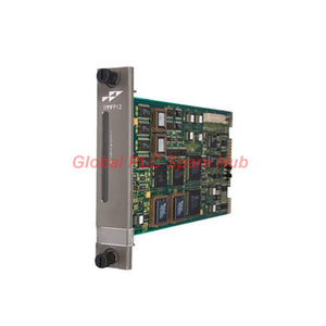
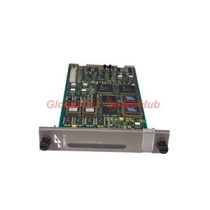
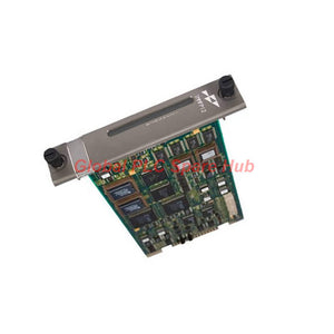
IMMFP12 ABB INFI 90 OPEN Multifunction Processor | Bailey DCS Control
Manufacturer: ABB
Product No.: IMMFP12
Condition: In stock
Product Type: Processor Module
Product Origin: USA
Payment: T/T, Western Union
Weight: 500g
Shipping port: Xiamen
Warranty: 12 months
Estimate delivery times: 12-26 days (International), 3-6 days (United States).
Return within 30 days of purchase. Duties & taxes are non-refundable.
Guaranteed Safe Checkout
IMMFP12 ABB Bailey Multifunction Processor Module for INFI 90 OPEN DCS
The ABB Bailey IMMFP12 Multifunction Processor Module is a control-processing component for the INFI 90 OPEN and Network 90 distributed control systems. It executes user-designed control strategies and coordinates data exchange with supported system modules through Controlway and the module bus.
Built around a 32-bit CPU operating at 16 MHz, the IMMFP12 supports analog, digital, batch, and advanced control applications. It manages communication with up to 64 I/O modules, making it relevant to process-control installations that require coordinated logic execution and rack-level data handling.
For maintenance engineers, selecting this module involves more than matching the model number. Verify the installed DCS architecture, termination hardware, communication wiring, control strategy requirements, and any redundant processor arrangement before replacing an existing unit.
Control Core | Processing, Memory, and System Capacity
| Specification | IMMFP12 Details |
|---|---|
| Manufacturer | ABB / Bailey Controls |
| Model | IMMFP12 |
| Product type | Multifunction Processor (MFP) Module |
| Supported system families | INFI 90 OPEN and Network 90 DCS |
| Processor | 32-bit CPU |
| CPU clock speed | 16 MHz |
| External bus | 16-bit |
| ROM | 512 kB |
| RAM | 512 kB, including 347,712 user bytes |
| NVRAM | 256 kB, including 194,752 user bytes |
| Power requirement | +5 V DC at 2 A, approximately 10 W |
| Rack occupancy | One slot |
| Operating modes | Execute, Configure, Error |
| Controlway communication | 1 Mbaud |
| I/O management capacity | Up to 64 I/O modules, subject to system configuration |
Control Strategy Execution | What the MFP Does
The IMMFP12 serves as a processing element within the DCS architecture. Its role is to execute configured control logic and coordinate supported system data, rather than act as a standalone PLC or field I/O module.
- Analog control: Executes configured analog control strategies using data provided by supported system modules.
- Digital logic: Handles user-designed digital control sequences and associated logic operations.
- Batch control: Supports configured batch-related control strategies where the system application and software provide the required functionality.
- Advanced control: Executes supported user-designed control strategies within the capabilities of the installed system.
- I/O coordination: Manages communication with supported I/O modules through the system's applicable bus architecture.
Actual control behavior depends on the loaded strategy, system configuration, connected modules, and application software. Replacing the processor does not automatically recreate the previous control configuration. Confirm the availability and validity of the required application and configuration data before a planned replacement.
Bus Architecture and Termination Hardware
The IMMFP12 supports Controlway and module-bus communication. Its termination arrangements are an important part of the installation because communication-port configuration and redundant processor wiring depend on the associated hardware.
| Component or interface | Function | Engineering consideration |
|---|---|---|
| Controlway | System communication at 1 Mbaud | Check bus connectivity and system status when communication between modules is interrupted. |
| Module bus | Communication with supported system modules | Verify rack and module configuration against the applicable system documentation. |
| NIMP01 termination module | Provides termination arrangements for the MFP installation | Jumpers configure the two RS-232-C ports for DTE or DCE operation. |
| RS-232-C ports | Serial communication interfaces through the applicable termination arrangement | Confirm the required DTE/DCE configuration and cable wiring. |
| RS-485 option | One RS-232-C port can be configured for RS-485 | Verify the supported configuration and wiring requirements before connecting the interface. |
| NIMP02 termination module | Required for installations using redundant MFP modules, according to the supplied product information | Confirm the redundant hardware arrangement and follow the NIMP02 installation instructions. |
Installation note: NIMP01 and NIMP02 serve different termination and installation requirements. Do not select a termination module solely by physical fit. Confirm the system configuration, serial-interface requirements, and redundancy arrangement in the applicable ABB/Bailey instructions.
Operating States and LED-Based Diagnostics
The module's indicators help maintenance personnel distinguish potential power or seating problems from primary/backup identification in a redundant arrangement. Interpret each indication in the context of the complete rack configuration.
| Indicator | Reported state | Diagnostic interpretation |
|---|---|---|
| Status LED | OFF | Possible loss of power, improper module seating, or a defective module. |
| Status LED | RED | Possible improper seating or module defect. |
| Status LED | GREEN | The supplied information identifies green as the normal condition; confirm the exact indication against the applicable manual. |
| 7/8 LED | OFF | Possible loss of power, improper module seating, or a defective module. |
| 7/8 LED | RED | Identifies the primary module in the reported redundant configuration. |
| 8 LED | OFF | Possible loss of power, improper module seating, or a defective module. |
| 8 LED | RED | Identifies the backup module in the reported redundant configuration. |
The 7/8 and 8 indicators should be interpreted according to the system's redundancy arrangement. A red indication on either of these indicators is described as a role indication in the supplied data, not automatically as a fault. Do not apply the status LED's red-state interpretation to the primary/backup indicators.
Field Troubleshooting | From Symptom to Root Cause
| Observed symptom | Checks to prioritize | Recommended response |
|---|---|---|
| Status LED remains OFF | Rack power availability, module seating, connector condition | Follow approved isolation procedures, verify the rack supply, and inspect module installation before considering replacement. |
| Status LED is RED | Seating, connector alignment, module condition, and applicable diagnostic records | Check the installation and consult the system manual for the exact indicator meaning and recovery procedure. |
| Control strategy does not execute as expected | Operating mode, loaded configuration, processor status, and related module communication | Determine whether the module is in Execute, Configure, or Error mode and investigate the associated system indications. |
| Communication with I/O modules is interrupted | Controlway or module-bus connections, rack configuration, and affected module status | Identify whether the fault affects one module or multiple modules, then trace the relevant bus and module path. |
| Serial communication fails | NIMP01 jumper settings, DTE/DCE selection, cabling, and RS-232-C or RS-485 configuration | Compare the termination settings with the connected equipment's interface requirements and the approved wiring diagram. |
| Redundant arrangement does not behave as expected | Primary/backup identification, NIMP02 installation, rack configuration, and redundancy-related system status | Verify the configured redundancy arrangement and follow the applicable switchover and recovery procedures. |
Maintenance caution: A module that appears defective may be affected by rack power, connector seating, termination wiring, or configuration issues. Preserve diagnostic records and verify the surrounding hardware before removing a processor from an operating DCS.
Where the IMMFP12 Fits in a Plant
- Process automation DCS: Executes configured control strategies in compatible INFI 90 OPEN and Network 90 installations.
- Oil and gas facilities: Supports control-system processing in suitable legacy process-control installations.
- Chemical and petrochemical plants: Provides processor functionality for supported process logic and analog control applications.
- Power generation and utilities: Can serve within compatible DCS architectures that coordinate process equipment and I/O.
- Industrial process lines: Supports batch, digital, analog, and advanced control strategies defined by the installed system.
- Legacy system maintenance: May be considered for replacement planning where the installed rack, processor configuration, termination hardware, and application requirements match.
These are potential application areas, not a guarantee of suitability for every plant or control strategy. Verify the exact system generation, installed hardware, application configuration, and site requirements before specifying the module.
Global PLC Spare HUB's Insight
When diagnosing an IMMFP12 issue, separate processor status, bus communication, and termination configuration into independent checks. This makes it easier to determine whether the symptom originates at the processor, the rack, the communication path, or the connected modules.
In redundant installations, first identify which module is configured as primary and which is backup. The supplied LED information uses red indications on the 7/8 and 8 indicators to distinguish these roles. Treating every red LED as a processor fault can lead to unnecessary replacement and incorrect troubleshooting conclusions.
For a planned replacement, document the operating mode, indicator states, termination-module type, serial-port jumper settings, and relevant control-system configuration before intervention. Confirm the approved recovery procedure and availability of the required control strategy data so that hardware replacement does not become an avoidable commissioning problem.
Global PLC Spare HUB Review
The ABB/Bailey IMMFP12 is a multifunction processor designed for established INFI 90 OPEN and Network 90 DCS architectures. Its 32-bit processor, stated memory configuration, Controlway support, and capacity to manage up to 64 I/O modules make it relevant to maintaining compatible control systems.
Its suitability depends on the installed system configuration rather than processing specifications alone. Buyers should confirm the exact model, rack compatibility, termination hardware, serial communication requirements, and redundant processor arrangement. For legacy DCS maintenance, these checks are especially important because a processor replacement may also require configuration validation and a controlled commissioning procedure.
Warranty, Packaging, and Shipping
- Warranty: 12-month warranty, subject to the seller's applicable warranty terms and conditions.
- Shipping options: FedEx, UPS, or DHL, subject to destination, carrier availability, and shipment requirements.
- Model verification: Confirm that the required part number is IMMFP12 before placing an order.
- Compatibility review: Provide the installed system family, rack details, and termination-module information when requesting a replacement.
Frequently Asked Questions
Q1: What should I verify before replacing an IMMFP12 in an operating DCS?
Confirm the installed system family, rack arrangement, termination module, processor role, and control strategy backup. Review the approved changeover procedure and ensure that the replacement can be configured for the target installation. Do not remove an operating processor until the site's isolation and process-continuity requirements have been addressed.
Q2: Does the IMMFP12 store the entire control application in nonvolatile memory?
The supplied specifications list ROM, RAM, and NVRAM capacities, including user-byte figures for RAM and NVRAM. They do not fully define how the installed application is stored or recovered. Consult the applicable system documentation and confirm the backup and restoration procedure before relying on a memory specification for replacement planning.
Q3: How can I distinguish a primary processor from a backup processor?
According to the supplied indicator information, a red 7/8 LED identifies the primary module, while a red 8 LED identifies the backup module in a redundant configuration. Verify the installed arrangement and the indicator definitions in the correct manual before performing a switchover or replacing either module.
Q4: What information helps determine whether NIMP01 or NIMP02 is required?
Check whether the installation needs serial-port termination and DTE/DCE selection, an RS-485 configuration, or redundant MFP hardware. The supplied information associates NIMP01 with serial-interface configuration and identifies NIMP02 as required for redundant MFP installations. Confirm the exact arrangement against the termination-module instructions.
Q5: Is a processor with normal LED indications necessarily ready to resume plant control?
Not necessarily. Normal-looking indicators do not prove that the correct control strategy is loaded, that all required I/O modules communicate correctly, or that process permissives are satisfied. Validate the operating mode, application configuration, bus status, and relevant process interlocks using the site's approved commissioning procedure.
Request a Quote for ABB IMMFP12
Looking for an ABB Bailey IMMFP12 Multifunction Processor Module for DCS maintenance or replacement? Contact Global PLC Spare HUB with your system family, rack configuration, and termination-module details to request pricing and compatibility support.
Tags
Q: Are these parts 100% original and new?
A: Yes. Every component is guaranteed to be 100% original, brand-new, and factory-sealed. We also provide a 12-month comprehensive warranty for your peace of mind.
Q: How fast is the shipping to my country?
A: For in-stock items, we offer same-day dispatch. International express shipping (DHL/FedEx/UPS) typically delivers within 3–5 business days worldwide.
Q: Can I get a formal quotation with shipping costs?
A: Absolutely. Our sales team is ready to provide a detailed Proforma Invoice (PI) including the most competitive shipping rates for your location.
Q: Do you offer discounts for bulk orders?
A: We provide volume-based pricing for large projects or multiple-item orders. Please contact us to get our Best Price Guarantee.
12-Month Comprehensive Warranty
Every part supplied by Global PLC Spare Hub is covered by a 12-month warranty from the date of invoice.
- Coverage: Functional defects and hardware failures under normal operating conditions.
- Commitment: We provide immediate repair, replacement, or a full refund for any verified defective components to minimize your operational downtime.
Returns & Exchange Policy
We offer a 30-day return policy to ensure you receive the exact part your system requires.
- Eligibility: Returns are accepted for uninstalled items in their original, factory-sealed packaging.
- RMA Process: Please contact our support team to obtain a Return Merchandise Authorization (RMA) number before shipping.
- Fast Processing: Refunds or exchanges are processed within 3–5 business days after the returned item passes our technical inspection.
Need Technical Assistance?Not sure if this part is compatible with your system? [Consult our Engineers] before purchasing to ensure 100% compatibility.
People Also Bought


