


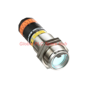
OID200 ifm OID Photoelectric Distance Sensor Laser ToF with IO-Link
Manufacturer: IFM
Product No.: OID200
Condition: In stock
Product Type: Photoelectric Distance Sensor
Product Origin: USA
Payment: T/T, Western Union
Weight: 300g
Shipping port: Xiamen
Warranty: 12 months
Estimate delivery times: 12-26 days (International), 3-6 days (United States).
Return within 30 days of purchase. Duties & taxes are non-refundable.
Guaranteed Safe Checkout
OID200 | ifm OID Photoelectric Distance Sensor with IO-Link
The ifm OID200 is a laser-based photoelectric distance sensor designed for industrial object detection and distance measurement. It uses time-of-flight (ToF) technology and background suppression to evaluate targets within its specified measuring range.
With a measuring range of 0.03 to 2 m, an M30 threaded housing, and integrated IO-Link communication, the OID200 supports machine automation tasks that require non-contact distance feedback. Its two PNP switching outputs provide discrete control signals, while IO-Link transfers process data and supports parameter access.
Ordering reference: OIDLCPKG/US. Confirm the exact order code, model designation, and regional version against the manufacturer's documentation before placing an order.
01 | Measurement Capability at a Glance
| Measurement Feature | Specification | Engineering Significance |
|---|---|---|
| Measuring principle | Laser time-of-flight (ToF) | Measures distance without physical contact with the target. |
| Measuring range | 0.03–2 m | Supports distance monitoring within the specified operating range. |
| Background suppression | Specified in supplied data as < 20 m | Verify the exact background-suppression definition and limit in the manufacturer's datasheet. |
| Light source | Red laser, 650 nm | Provides a visible aiming point for installation and alignment. |
| Laser classification | Class 2, maximum output ≤ 4.0 mW as supplied | Follow the manufacturer's laser safety instructions and applicable standards. |
| Sampling rate | 33 Hz | Defines the stated measurement sampling rate. |
| Switching frequency | 11 Hz | Consider this limit when evaluating response requirements for moving targets. |
| Detection hysteresis | < 2%; black target at 6% remission background noted | Target reflectivity can influence switching behavior and repeatability. |
| Maximum light spot diameter | 5 mm at 2 m | Check target size and alignment at the maximum measurement distance. |
| Ambient light immunity | Up to 10 klx on the object | Evaluate performance under the actual lighting conditions. |
| Typical light source lifetime | 50,000 hours | Use this figure as a typical source-life specification, not a guaranteed sensor service life. |
02 | Mechanical Design and Installation Envelope
The cylindrical M30 housing simplifies integration into compatible machine brackets and threaded mounting points. The supplied package includes two stainless steel M30 lock nuts for mounting.
- Housing format: M30 × 1.5 threaded cylinder.
- Overall length: 100 mm.
- Weight: 207 g.
- Housing material: Stainless steel.
- Front pane: PMMA.
- LED window: PC.
- Other listed materials: PBT and FKM.
- Electrical connection: One M12 A-coded, four-pin connector.
- Ingress protection: IP65 and IP67, as specified.
Before installation, check the available mounting depth, connector clearance, target alignment, and cable bend space. Confirm chemical compatibility for exposed materials when the sensor operates near cleaning agents, oils, or process fluids.
03 | Electrical Interface and Switching Logic
| Electrical Parameter | Rated Specification |
|---|---|
| Supply voltage | 10–30 V DC |
| Current consumption | 75 mA at 24 V |
| Output configuration | 2 × PNP, complementary NO/NC |
| Maximum output load | 100 mA per output |
| Switching frequency | 11 Hz |
| Short-circuit protection | Yes, pulsed |
| Overload protection | Yes |
| Reverse-polarity protection | Yes |
| Protection class | III |
| EMC reference | EN 60947-5-2 |
| MTTF | 239 years, as specified |
The complementary PNP outputs can support PLC input logic and object-state monitoring. Verify the required NO/NC behavior, input voltage compatibility, and channel current limits before wiring the sensor.
Do not treat the 33 Hz sampling rate as the switching frequency. The supplied specifications list these as separate parameters, and application response must meet the actual switching requirement.
04 | IO-Link Communication and Process Data
The OID200 integrates an IO-Link interface through its M12 A-coded four-pin connector. It supports IO-Link communication and standard SIO operation, allowing integration into systems that use either IO-Link process data or conventional switching signals.
| Communication Parameter | Specification |
|---|---|
| IO-Link revision | 1.1 |
| Transmission rate | COM2, 38.4 kBaud |
| SIO mode | Supported |
| Standard | IEC 61131-9 |
| Sensor profile | SSP 0, generic profiled sensor |
| Default DeviceID | 373 |
| Minimum process cycle | 6.4 ms |
| Process data | One analogue value and one binary value |
| Communication expansion | No separate expansion interface listed |
For IO-Link integration, confirm the master port configuration, sensor DeviceID, process-data mapping, and PLC variable assignment. Use the manufacturer's IODD and device documentation when available to configure parameters correctly.
05 | Suitable Equipment and Industrial Applications
- Conveyor systems: Monitor object distance or presence at transfer points and inspection stations.
- Packaging machinery: Check product position and support non-contact detection where the target falls within the rated range.
- Assembly automation: Provide distance feedback for workpiece positioning and sequence checks.
- Material handling: Detect objects at defined distances on automated handling equipment.
- Machine tending: Support presence or position checks around fixtures and loading stations.
- PLC-controlled inspection stations: Deliver switching signals and IO-Link process data for control logic and monitoring.
Application suitability depends on target dimensions, surface reflectivity, installation angle, ambient light, and required response time. Validate performance with the actual workpiece rather than relying only on nominal range.
06 | Field Diagnostics and Commissioning Workflow
When the sensor reports an incorrect distance or produces unstable switching, check the optical setup before changing PLC logic. Surface properties, alignment, supply voltage, and communication configuration can all affect system behavior.
| Observed Symptom | Checks to Perform | Diagnostic Purpose |
|---|---|---|
| No detection at the target | Check the 10–30 V DC supply, target position, and measurement range. | Separate power and alignment issues from range limitations. |
| Intermittent switching | Inspect target reflectivity, vibration, alignment, and ambient light. | Identify optical conditions that may destabilize detection. |
| Incorrect PLC input state | Verify PNP input compatibility, NO/NC logic, and wiring. | Distinguish output-logic errors from measurement problems. |
| Missing IO-Link process data | Check the master port mode, M12 connection, DeviceID, and process-data mapping. | Identify configuration or communication faults. |
| Unexpected response on fast-moving targets | Compare the application cycle with the specified 11 Hz switching frequency. | Determine whether the sensor meets the required response rate. |
| Sensor inactive during cold startup | Check ambient temperature and the warm-up requirement below −10 °C. | Confirm whether the sensor is operating within its startup conditions. |
The yellow LED indicates the switching output associated with pin 4, while the green LED indicates operation. The display supports centimetre or inch units, and the setting ring provides local adjustment.
At ambient temperatures below −10 °C, the supplied specification states that warm-up is required and the laser remains off during this period. Follow the manufacturer's startup instructions before diagnosing a suspected failure.
07 | Global PLC Spare HUB's Insight
In practical machine integration, the most common selection mistake is choosing a distance sensor by range alone. The OID200's 2 m maximum range does not guarantee stable detection on every surface or at every angle.
For conveyor applications, test the smallest and least reflective workpieces at the actual installation distance. Check the 5 mm maximum light spot diameter at 2 m against the target's usable surface area.
For PLC projects, assess the switching frequency separately from the IO-Link process cycle. A communication cycle of 6.4 ms does not automatically mean the physical output can switch at the same rate.
For replacement projects, compare the model, order code, connector, mounting dimensions, output type, and IO-Link settings. Confirm the device identity before downloading parameters or changing a master-port configuration.
08 | Environmental Limits and Selection Notes
| Environmental Item | Specification or Limitation |
|---|---|
| Operating temperature | −25 to 60 °C |
| Cold-start condition | Warm-up required below −10 °C; laser off during warm-up, as supplied |
| Storage temperature | Not listed in the supplied technical data |
| Relative humidity | Not listed in the supplied technical data |
| Ingress protection | IP65 and IP67 |
| Laser safety | Class 2; observe manufacturer safety instructions |
Do not infer a storage-temperature or relative-humidity rating from the operating-temperature range. Consult the manufacturer's documentation when the installation requires defined storage or humidity limits.
09 | Product Identification, Warranty and Shipping
- Brand: ifm
- Model: OID200
- Series: OID photoelectric distance sensor
- Product type: Laser time-of-flight distance sensor with background suppression and IO-Link
- Ordering reference supplied: OIDLCPKG/US; verify against the exact model and regional order code before purchase.
- Warranty: 12 months, subject to the seller's written warranty terms.
- Shipping methods: FedEx, UPS, and DHL, subject to destination and shipping arrangements.
- Package contents: Confirm the exact supplied accessories and mounting hardware with the seller.
10 | Frequently Asked Questions
Q1: How should I select the measuring range for a real machine installation?
A: Measure the minimum and maximum target distances, then allow for mechanical tolerances and target movement. Test representative workpieces under actual lighting conditions before approving the installation.
Q2: Will the OID200 detect dark or low-reflectivity objects reliably?
A: Performance depends on surface reflectivity, target geometry, and installation conditions. Validate the least reflective target during commissioning rather than assuming every object performs identically.
Q3: Can I connect the sensor directly to a standard PLC digital input?
A: The sensor provides PNP switching outputs, but the PLC input must support the required voltage and current. Confirm the wiring diagram and NO/NC logic before connecting the device.
Q4: What should I check before replacing an existing IO-Link sensor with this model?
A: Compare the measuring range, housing dimensions, connector, output logic, process-data format, and master compatibility. Also verify the exact order code and device identity before reusing stored parameters.
Q5: What information helps diagnose a sensor that works locally but fails through IO-Link?
A: Record the master model, port mode, device identification, connection status, and process-data mapping. Check the M12 cable and master diagnostics before replacing the sensor.
Request a Quote from Global PLC Spare HUB
Contact Global PLC Spare HUB for pricing, order-code verification, and compatibility guidance for the ifm OID200. Include your application distance, target material, PLC or IO-Link master model, and required quantity to support a more accurate selection.

Tags
Q: Are these parts 100% original and new?
A: Yes. Every component is guaranteed to be 100% original, brand-new, and factory-sealed. We also provide a 12-month comprehensive warranty for your peace of mind.
Q: How fast is the shipping to my country?
A: For in-stock items, we offer same-day dispatch. International express shipping (DHL/FedEx/UPS) typically delivers within 3–5 business days worldwide.
Q: Can I get a formal quotation with shipping costs?
A: Absolutely. Our sales team is ready to provide a detailed Proforma Invoice (PI) including the most competitive shipping rates for your location.
Q: Do you offer discounts for bulk orders?
A: We provide volume-based pricing for large projects or multiple-item orders. Please contact us to get our Best Price Guarantee.
12-Month Comprehensive Warranty
Every part supplied by Global PLC Spare Hub is covered by a 12-month warranty from the date of invoice.
- Coverage: Functional defects and hardware failures under normal operating conditions.
- Commitment: We provide immediate repair, replacement, or a full refund for any verified defective components to minimize your operational downtime.
Returns & Exchange Policy
We offer a 30-day return policy to ensure you receive the exact part your system requires.
- Eligibility: Returns are accepted for uninstalled items in their original, factory-sealed packaging.
- RMA Process: Please contact our support team to obtain a Return Merchandise Authorization (RMA) number before shipping.
- Fast Processing: Refunds or exchanges are processed within 3–5 business days after the returned item passes our technical inspection.
Need Technical Assistance?Not sure if this part is compatible with your system? [Consult our Engineers] before purchasing to ensure 100% compatibility.
People Also Bought


