


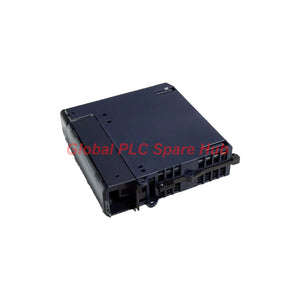
IC694MDL742 GE Fanuc RX3i PACSystems DC Output Module
Manufacturer: GE Fanuc
Product No.: IC694MDL742
Condition: In stock
Product Type: DC Output Module
Product Origin: USA
Payment: T/T, Western Union
Weight: 300g
Shipping port: Xiamen
Warranty: 12 months
Estimate delivery times: 12-26 days (International), 3-6 days (United States).
Return within 30 days of purchase. Duties & taxes are non-refundable.
Guaranteed Safe Checkout
IC694MDL742 GE Fanuc RX3i PACSystems 16-Point DC Output Module
The GE Fanuc IC694MDL742 is a 16-point DC discrete output module designed for compatible RX3i PACSystems PLC installations. It operates with 12/24 VDC field circuits and divides its outputs into two independently protected groups of eight points.
Its electronic short-circuit protection (ESCP) helps limit the impact of output-circuit faults. When the protection detects a short circuit, it can disable affected output points and activate the fault indication. This grouped protection architecture helps maintenance personnel narrow the fault to the relevant output section before checking individual field circuits.
The IC694MDL742 supports negative-logic operation and provides individual output status LEDs. Field devices require an appropriate external power source. Engineers should verify load compatibility, wiring polarity, group loading, and backplane requirements before installation.
01 | Output Architecture: Two Groups, One Diagnostic Strategy
| Output section | Point allocation | Protection arrangement | Maintenance focus |
|---|---|---|---|
| Group 1 | Outputs 1–8 | Electronic short-circuit protection for the group | Check the field supply, wiring, and connected loads for the first group. |
| Group 2 | Outputs 9–16 | Electronic short-circuit protection for the group | Inspect the second group's wiring and loads independently. |
Signal path: PLC output command → output channel → external DC load circuit → field device response.
Protection path: Short-circuit detection → affected output shutdown → fault indication → field-circuit inspection → recovery according to the manufacturer's procedure.
The two ESCP groups help localize troubleshooting, but they do not replace branch-level protection, correct wiring practices, or load-current calculations. Verify the manufacturer's recovery procedure before restoring a tripped output group.
02 | Electrical and Hardware Specifications
| Parameter | Specification |
|---|---|
| Manufacturer | GE Fanuc Automation |
| Brand | GE Fanuc |
| Catalog number | IC694MDL742 |
| Product series | RX3i PACSystems |
| Module type | Discrete DC output module |
| Number of outputs | 16 points |
| Output grouping | 2 groups of 8 points |
| Rated field voltage | 12/24 VDC |
| Logic arrangement | Negative logic, as supplied |
| Maximum output current | 1 A per point, as supplied |
| Voltage tolerance | -15% to +20%, as supplied |
| Electronic short-circuit protection | Yes, one protection function for each group of 8 outputs |
| Output status indicators | Individual numbered LEDs |
| Fault indication | Fault LED activation following a detected protection event, as supplied |
| Isolation | 250 VAC continuous, as supplied |
| Power consumption | 130 mA, reported with all outputs ON; verify the applicable supply reference |
| Inrush current | 5.2 A for 10 ms, as supplied |
| Hot insertion/removal | Supported under specified RX3i universal backplane conditions |
| Field load supply | External power source required |
Specification check: Confirm the official module documentation for the precise output-current conditions, group-level current limits, isolation test definition, and supply reference for the 130 mA figure. The maximum current per point should not be treated as permission to operate all 16 points at 1 A simultaneously without checking group, thermal, and system limits.
03 | Load Engineering: Check Before Energizing
Output compatibility depends on more than nominal voltage. Before assigning field devices to the IC694MDL742, evaluate the electrical characteristics of each load and the combined demand on each protected group.
- Voltage matching: Confirm that the field supply and load operating voltage fall within the module's documented limits.
- Steady-state current: Check each solenoid, relay, contactor interface, or indicator against the permitted point-current rating.
- Inrush demand: Consider coil energization and capacitive loads. A load can draw substantially more current during startup than during normal operation.
- Group loading: Calculate the total demand for outputs 1–8 and outputs 9–16 separately. Confirm both groups satisfy the manufacturer's limits.
- Inductive energy: Assess the suppression requirements for DC coils and other inductive loads. Select suitable suppression components according to the load and control design.
- Negative-logic behavior: Verify the module's electrical interface and the application's ON/OFF interpretation before commissioning.
04 | Typical Industrial Applications
| Application | Example loads | Engineering purpose |
|---|---|---|
| Machine automation | DC indicator lamps, compatible relay interfaces | Execute discrete commands from PLC sequence logic. |
| Conveyor systems | Interface relays and compatible control loads | Coordinate operating sequences and equipment states. |
| Packaging machinery | Compatible pneumatic valve solenoids and auxiliary control circuits | Control discrete actions such as clamping, diverting, and positioning. |
| Process skids | DC control interfaces and status-related output circuits | Operate configured devices within a PLC-controlled process. |
| Legacy RX3i installations | Existing compatible 12/24 VDC field loads | Maintain established output assignments while preserving verified hardware compatibility. |
These are representative application examples, not a guarantee that every listed device can connect directly. Confirm load current, switching characteristics, suppression needs, and interface requirements before wiring a field device to an output point.
05 | Fault Isolation: Use the Group Protection as a Diagnostic Clue
| Observed symptom | Possible cause | Recommended engineering check |
|---|---|---|
| Fault LED activates after a load is switched ON | Short circuit, damaged cable, incorrect field wiring, or an overloaded output circuit | Isolate the affected field circuit using the approved procedure and inspect wiring and load resistance before re-energizing. |
| Several outputs in one group stop operating | Group-level protection has operated, or a shared supply or wiring fault exists | Identify whether the affected points belong to outputs 1–8 or 9–16. Check the group supply and all connected branches. |
| One output does not operate the load | Incorrect logic command, open conductor, missing external supply, or load failure | Compare the PLC command, channel LED, field voltage, and actual load response. |
| Output appears commanded but the actuator does not move | Open coil, mechanical binding, failed interface relay, or insufficient load voltage | Measure the field circuit under operating conditions and inspect the actuator and intermediate devices. |
| Protection reactivates after a reset or restoration attempt | The short circuit or overload remains, or the load exceeds the permitted operating conditions | Keep the circuit isolated until the root cause is identified. Do not repeatedly restore power to a suspected fault. |
| LED status and actual equipment state disagree | Field supply failure, wiring fault, load failure, or a mismatch between command and physical feedback | Compare the PLC output command, module indication, measured voltage, and independent equipment feedback. |
Field troubleshooting sequence: Record the affected output numbers, identify their protection group, inspect the external supply, and check the load and wiring. Restore operation only after correcting the fault and following the manufacturer's reset or recovery procedure.
The output LEDs indicate channel status; they do not independently confirm that the connected actuator has moved or completed its task. Where equipment feedback is required, use a suitable independent feedback signal in the control design.
06 | Global PLC Spare HUB Review
The IC694MDL742 is worth considering when maintaining a compatible RX3i output system that needs 16 discrete DC output points and group-based electronic short-circuit protection. Its two-group layout provides a useful troubleshooting boundary when several loads share a protected output section.
For replacement planning, verify the complete catalog number, rack and backplane compatibility, output wiring, logic arrangement, field voltage, and load-current requirements. Pay particular attention to inductive loads and startup current, since these can affect output reliability even when the nominal load current appears acceptable.
Hot insertion and removal are listed as supported features, but this does not mean every rack, system configuration, or maintenance procedure permits unrestricted live removal. Follow the applicable RX3i documentation and site safety procedures before handling an energized module.
07 | Ordering, Warranty and Shipping
- Product: GE Fanuc IC694MDL742 RX3i PACSystems DC output module
- Condition: New and original in factory packing, subject to order confirmation
- Warranty: 12 months, subject to the seller's applicable warranty terms
- Shipping methods: FedEx, UPS, or DHL, depending on destination and service availability
- Compatibility review: Share the catalog number, rack configuration, field voltage, and load type when requesting a quotation.
08 | Frequently Asked Questions
Q1. How do I determine whether a DC solenoid is suitable for this output module?
Answer: Compare the solenoid's rated voltage, steady-state current, inrush behavior, and inductive suppression requirements with the module specifications. Also calculate the total load for its eight-point protection group. If the load characteristics are uncertain, obtain the manufacturer's data before connecting it.
Q2. What should I check if a replacement module works with small loads but trips with a contactor or valve?
Answer: Investigate startup current, coil characteristics, wiring insulation, and the combined load on the relevant group. A larger load can expose an overload or short-circuit condition that a low-current test does not reveal. Verify the permitted switching and load conditions before returning the circuit to service.
Q3. Does electronic short-circuit protection eliminate the need for external circuit protection?
Answer: No. ESCP is a module protection feature, not a universal substitute for correctly selected branch protection and installation practices. Follow the system manufacturer's instructions and applicable electrical standards when designing field power distribution and protective devices.
Q4. Can I replace the IC694MDL742 with any 16-point 24 VDC output module?
Answer: No. Modules with the same point count and nominal voltage may differ in output polarity, electrical topology, current limits, terminal arrangement, group protection, and backplane compatibility. Verify the complete catalog number and system requirements before approving an alternative.
Q5. What information should I send when requesting a quotation for this spare?
Answer: Provide the IC694MDL742 catalog number, required quantity, installed RX3i rack or backplane details, field voltage, and the type of connected loads. Also confirm your required condition, warranty expectations, destination, and delivery urgency. These details help the supplier review compatibility and available shipping options before order confirmation.
Tags
Q: Are these parts 100% original and new?
A: Yes. Every component is guaranteed to be 100% original, brand-new, and factory-sealed. We also provide a 12-month comprehensive warranty for your peace of mind.
Q: How fast is the shipping to my country?
A: For in-stock items, we offer same-day dispatch. International express shipping (DHL/FedEx/UPS) typically delivers within 3–5 business days worldwide.
Q: Can I get a formal quotation with shipping costs?
A: Absolutely. Our sales team is ready to provide a detailed Proforma Invoice (PI) including the most competitive shipping rates for your location.
Q: Do you offer discounts for bulk orders?
A: We provide volume-based pricing for large projects or multiple-item orders. Please contact us to get our Best Price Guarantee.
12-Month Comprehensive Warranty
Every part supplied by Global PLC Spare Hub is covered by a 12-month warranty from the date of invoice.
- Coverage: Functional defects and hardware failures under normal operating conditions.
- Commitment: We provide immediate repair, replacement, or a full refund for any verified defective components to minimize your operational downtime.
Returns & Exchange Policy
We offer a 30-day return policy to ensure you receive the exact part your system requires.
- Eligibility: Returns are accepted for uninstalled items in their original, factory-sealed packaging.
- RMA Process: Please contact our support team to obtain a Return Merchandise Authorization (RMA) number before shipping.
- Fast Processing: Refunds or exchanges are processed within 3–5 business days after the returned item passes our technical inspection.
Need Technical Assistance?Not sure if this part is compatible with your system? [Consult our Engineers] before purchasing to ensure 100% compatibility.
People Also Bought


