


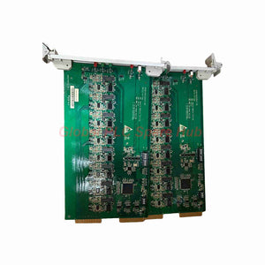
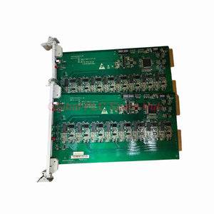
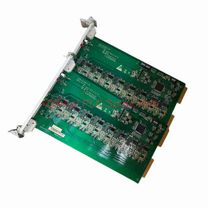
BDO20 388A2275P0176V1 GE Terminal Board | Mark VIe I/O Interface
Manufacturer: GE
Product No.: BDO20
Condition: In stock
Product Type: Terminal Board
Product Origin: USA
Payment: T/T, Western Union
Weight: 500g
Shipping port: Xiamen
Warranty: 12 months
Estimate delivery times: 12-26 days (International), 3-6 days (United States).
Return within 30 days of purchase. Duties & taxes are non-refundable.
Guaranteed Safe Checkout
GE BDO20 Terminal Board | 388A2275P0176V1
Reliable field wiring starts with the correct interface between control electronics and external circuits. The GE BDO20 388A2275P0176V1 is identified as a terminal board designed for industrial control applications requiring organized I/O connections.
Its specified interface uses two 50-pin DIN-style backplane connectors and pluggable screw-clamp terminal blocks. The listed design includes 52 terminal positions and supports passive signal routing without active signal processing or power conversion.
Engineers should verify the exact hardware revision and system compatibility before installation. The BDO20 designation alone does not confirm support across every GE control platform or I/O configuration.
01 | Hardware Identity and Interface Architecture
| Parameter | Specification |
|---|---|
| Manufacturer | GE (General Electric) |
| Product Family | BDO20 |
| Part Number | 388A2275P0176V1 |
| Product Type | Industrial I/O terminal board |
| Backplane Interface | Two 50-pin DIN-style connectors, as specified |
| Terminal Arrangement | 52-position pluggable screw-clamp design |
| Signal Architecture | Passive signal passthrough |
| Active Electronics | No active components or power conversion, according to the supplied specifications |
| Voltage Rating | 300 V AC/DC, as specified |
| Current Rating | 10 A per pole, as specified |
| Operating Temperature | −40 °C to +85 °C, as specified |
| Storage Temperature | −55 °C to +100 °C, as specified |
| Humidity | Up to 95% RH, non-condensing, as specified |
Important: Confirm the electrical ratings, terminal assignments, and environmental limits against the applicable manufacturer documentation. These values do not establish the ratings of every connected I/O module or field circuit.
02 | Signal Routing and Electrical Design
The terminal board provides a physical interface for connecting compatible control-system signals to field wiring. Its passive design does not independently generate, convert, or condition signals.
- Backplane Connectivity: The two 50-pin connectors provide the specified interface to a compatible BDO20 carrier.
- Field Termination: Screw-clamp terminals support organized conductor termination and maintenance access.
- Signal Continuity: Passive routing carries signals through the board without active processing.
- Isolation Strategy: The supplied information attributes electrical isolation to individual I/O modules, not the terminal board itself.
- Power Boundaries: The board does not perform power conversion. Verify the source, load, and protection arrangements separately.
Do not treat passive signal routing as proof of galvanic isolation. Confirm the isolation method and withstand ratings for the complete I/O channel using the system documentation.
03 | Where the BDO20 Fits in Industrial Control
The supplied description associates BDO20 hardware with GE industrial control cabinets. However, the exact platform compatibility of 388A2275P0176V1 requires verification against the relevant equipment drawings and parts lists.
| Application Area | Potential Engineering Use | Compatibility Check |
|---|---|---|
| Power Generation | Field wiring interfaces within a supported control cabinet | Verify the controller platform and approved board assembly |
| Turbine Control | Signal termination for designated control circuits | Confirm the turbine control system and hardware revision |
| Industrial Process Control | Organized connections between field circuits and compatible I/O hardware | Check signal type, channel assignment, and wiring diagrams |
| Control Cabinet Maintenance | Replacement of a matching terminal board assembly | Compare the complete part number and connector arrangement |
| System Integration | Field wiring for a documented I/O configuration | Verify the approved system design and electrical ratings |
Platform note: Do not assume that every BDO20 board supports Mark VIe, Mark VIeS, or Nexus systems. Confirm the exact application using GE documentation before ordering.
04 | Channel Configuration and Selection Checks
Some supplied descriptions associate BDO20 configurations with 16-channel applications. The available information does not independently confirm that channel count for every 388A2275P0176V1 assembly.
- Verify the channel count and signal type in the equipment bill of materials.
- Confirm whether the target application uses digital inputs, digital outputs, or a specific relay interface.
- Match the terminal numbering to the approved connection diagram.
- Check connector keying, mechanical dimensions, and carrier compatibility.
- Review conductor size, termination requirements, and circuit protection.
- Confirm whether the project requires version V1 or another hardware revision.
Never substitute a V2 assembly for V1 based on appearance alone. Compare electrical interfaces, wiring assignments, revision requirements, and approved part lists before making a replacement decision.
05 | Installation and Commissioning Procedure
- Document the Existing Assembly: Record the part number, revision, terminal labels, connector positions, and wiring arrangement.
- Isolate Field Circuits: Apply site lockout procedures and verify the relevant circuits are safe to handle.
- Inspect the Board: Check the connectors, terminal blocks, mounting points, and PCB surfaces for damage.
- Check Connector Alignment: Verify the two 50-pin connectors match the intended carrier before engagement.
- Terminate Conductors: Follow the approved wiring diagram and specified terminal tightening requirements.
- Verify Circuit Ratings: Confirm that connected voltage, current, and protection remain within applicable limits.
- Perform Continuity Checks: Use approved procedures to verify intended signal paths while protecting connected electronics.
- Complete Functional Testing: Confirm the correct channel response through the host controller and approved commissioning process.
Practical tip: Photograph the original wiring before disconnection. This provides a useful reference when terminal labels are difficult to read or several similar conductors enter the same assembly.
06 | Fault Isolation and Diagnostic Approach
The terminal board provides signal interconnection rather than independent diagnostics. Engineers should use controller status information, electrical measurements, and wiring documentation to locate faults.
| Fault Symptom | Recommended Checks | Diagnostic Purpose |
|---|---|---|
| Multiple channels lose signals | Inspect backplane engagement and shared wiring paths | Identify a possible common connection fault |
| One channel shows an incorrect state | Check the field conductor, terminal assignment, and I/O channel configuration | Separate wiring faults from module or logic issues |
| Intermittent signal behavior | Inspect terminal security, conductor condition, and connector seating | Find loose or mechanically stressed connections |
| Unexpected voltage at a terminal | Verify the circuit drawing and measure under an approved test procedure | Identify wiring errors or external circuit conditions |
| Fault persists after board replacement | Check the I/O module, field device, configuration, and upstream supply | Avoid repeated replacement without evidence |
Field example: A technician observes that several input channels become unstable after cabinet maintenance. The technician first checks the shared connector seating and terminal wiring. If the problem remains, the technician compares controller diagnostics with field-side measurements. This sequence helps distinguish a common interconnection problem from individual sensor or I/O faults.
Never disconnect or probe energized circuits without an approved procedure. Use the system's electrical safety requirements and manufacturer test instructions.
07 | Global PLC Spare HUB's Insight
Terminal boards deserve careful revision control because connector fit alone does not guarantee correct signal mapping. A visually similar assembly can still differ in terminal assignments or system-specific implementation.
For the 388A2275P0176V1, engineers should prioritize three checks: the full part number, the carrier interface, and the field wiring diagram. The stated 300 V AC/DC and 10 A per-pole ratings also require confirmation against the actual circuit conditions and manufacturer documentation.
When troubleshooting several affected channels, inspect shared connections before assuming that multiple I/O modules have failed simultaneously. Record the initial symptoms, connector condition, measured values, and corrective actions. This evidence improves root-cause analysis and supports more reliable maintenance decisions.
08 | Ordering, Packaging, and Warranty
- Manufacturer: GE
- Product: BDO20 Terminal Board
- Part Number: 388A2275P0176V1
- Package Contents: One terminal board, subject to order confirmation. Additional connectors, accessories, or documents are included only when specified.
- Warranty: 12 months, subject to applicable seller warranty terms.
- Shipping Options: FedEx, UPS, or DHL, depending on destination and service availability.
- Dispatch Target: Typically 24–48 hours after order confirmation, subject to stock availability and order processing.
Contact Global PLC Spare HUB to confirm the exact revision, package contents, stock status, shipping arrangements, and warranty coverage before ordering.
09 | Certification and Environmental Compliance
The supplied specifications list operating and storage temperature limits and a non-condensing humidity rating. They do not identify specific safety, hazardous-area, or EMC certifications.
For regulated projects, request the applicable manufacturer documentation and verify the required approvals. Do not infer certification from the voltage rating or environmental limits alone.
10 | Frequently Asked Questions
Q1: Why should I verify the terminal mapping even when the replacement connectors fit?
Mechanical compatibility does not guarantee identical electrical routing. Compare the terminal assignments and approved wiring diagrams to prevent incorrect signals from reaching field circuits.
Q2: Does a passive terminal board provide channel-to-channel electrical isolation?
Not according to the supplied description. It attributes isolation to individual I/O modules. Confirm the actual isolation architecture and ratings for the complete installed assembly.
Q3: How can I distinguish a terminal board fault from an I/O module fault?
Compare controller diagnostics with approved field-side measurements and continuity checks. Inspect shared connections first, then isolate the affected channel according to the system troubleshooting procedure.
Q4: What should I verify before using this board in a high-current circuit?
Check the applicable voltage and current ratings, conductor specifications, terminal tightening requirements, circuit protection, and load characteristics. Do not rely on the stated 10 A rating without confirming its conditions of use.
Q5: Which details matter most when choosing between V1 and V2?
Compare the full part number, revision documentation, connector pinout, terminal layout, supported I/O configuration, and approved replacement list. Ask the supplier to verify the exact revision against your equipment details.
Request a Technical Quote
Need the GE BDO20 388A2275P0176V1 Terminal Board for an industrial control maintenance or integration project? Contact Global PLC Spare HUB for pricing, availability, and part-number compatibility checks.
Include the host system model, existing board revision, required quantity, and destination. These details help the team review your request and confirm the appropriate supply option.
Tags
Q: Are these parts 100% original and new?
A: Yes. Every component is guaranteed to be 100% original, brand-new, and factory-sealed. We also provide a 12-month comprehensive warranty for your peace of mind.
Q: How fast is the shipping to my country?
A: For in-stock items, we offer same-day dispatch. International express shipping (DHL/FedEx/UPS) typically delivers within 3–5 business days worldwide.
Q: Can I get a formal quotation with shipping costs?
A: Absolutely. Our sales team is ready to provide a detailed Proforma Invoice (PI) including the most competitive shipping rates for your location.
Q: Do you offer discounts for bulk orders?
A: We provide volume-based pricing for large projects or multiple-item orders. Please contact us to get our Best Price Guarantee.
12-Month Comprehensive Warranty
Every part supplied by Global PLC Spare Hub is covered by a 12-month warranty from the date of invoice.
- Coverage: Functional defects and hardware failures under normal operating conditions.
- Commitment: We provide immediate repair, replacement, or a full refund for any verified defective components to minimize your operational downtime.
Returns & Exchange Policy
We offer a 30-day return policy to ensure you receive the exact part your system requires.
- Eligibility: Returns are accepted for uninstalled items in their original, factory-sealed packaging.
- RMA Process: Please contact our support team to obtain a Return Merchandise Authorization (RMA) number before shipping.
- Fast Processing: Refunds or exchanges are processed within 3–5 business days after the returned item passes our technical inspection.
Need Technical Assistance?Not sure if this part is compatible with your system? [Consult our Engineers] before purchasing to ensure 100% compatibility.
People Also Bought


