


531X307LTBAJG1 GE EX2000 LAN I/O Terminal Board New Stock
Manufacturer: GE
Product No.: 531X307LTBAJG1
Condition: In stock
Product Type: Terminal Board
Product Origin: USA
Payment: T/T, Western Union
Weight: 500g
Shipping port: Xiamen
Warranty: 12 months
Estimate delivery times: 12-26 days (International), 3-6 days (United States).
Return within 30 days of purchase. Duties & taxes are non-refundable.
Guaranteed Safe Checkout
Product Overview
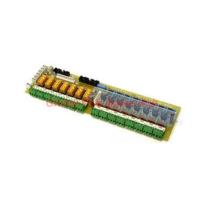
The 531X307LTBAJG1 is a high-reliability LAN I/O Terminal Board engineered by General Electric for the EX2000 excitation and drive series. This card establishes a robust control interface between core drive control processing units and external plant machinery. Operating within the drive cabinet, it processes eight configurable control inputs and seven Form C relay outputs to manage critical field signals without mechanical latency.
As a Group 1 (G1) configuration, the 531X307LTBAJG1 utilizes eight dedicated 24VDC programmable input plugs (CI1PL through CI8PL) routed via the 8PL bus structure. This architectural layout facilitates continuous, bidirectional signal routing between the LAN Terminal Board, the auxiliary NTB/3TB terminal boards, and the main drive control board. The onboard circuitry translates high-voltage field signals down to clean 24VDC logic levels for safe execution.
Global PLC Spare HUB's Insight
The 531X307LTBAJG1 is highly valued by controls engineers due to its dual-level isolation topology and hybrid I/O termination architecture. It splits field connections between high-density ribbon cable plug-in connectors (PL) for clean internal rack routing, and heavy-duty terminal block screws (TB) for rugged field wires. By supporting wide-range 24V to 240V AC/DC inputs on its main terminal array, this board gives retrofitted legacy systems immense flexibility while providing reliable signal isolation from hostile industrial electromagnetic environments.
Technical Specifications
- Brand: General Electric (GE)
- Model: 531X307LTBAJG1
- Series: EX2000 Control and Excitation System
- Module Type: LAN Local Terminal Board (LTB)
- Configurable Control Inputs: 8 points via CI1PL-CI8PL plugs (24VDC logic)
- Terminal Inputs: 8 point-to-point terminals (IN1 to IN8) accepting 24V to 240V AC or DC signals
- Control Relay Outputs: 7 low-voltage, low-current Form C relays (OT1 to OT7) featuring 3 terminals each
- High-Voltage Actuation: Integrated pilot contact connections for heavy-duty, high-current relay coils
- Turn-On Threshold: 6V, 0.5mA peak AC/DC signal level
- Turn-Off Threshold: 6V, 0.5mA peak AC/DC signal level
- Adjustable Components: None (solid-state fixed hardware design)
- Origin: United States of America (USA)
Diagnostic Capabilities & Status Indicators
- Onboard real-time diagnostic visual matrix utilizing 15 active LED indicators mapped directly to I/O logic.
- LED1 through LED8 illuminate instantly when an active voltage source is sensed on field circuits IN1 through IN8.
- LED17 through LED23 illuminate in sequence when command execution energizes field relays RX1 through RX7.
- Solid-state voltage sensing monitors the ON/OFF voltage transitions continuously against exact 6V thresholds.
Target Equipment & Application Scenarios
- GE EX2000 generator excitation cabinets managing large industrial synchronous motor fields.
- Heavy-duty industrial DC motor drives requiring centralized terminal interfacing for external control operators.
- Main line contactor coordination panels coupled with emergency stop and safety interlock strings.
- Power plant control infrastructure integrating remote control pushbuttons and status indication light arrays.
Installation & Wiring Guidelines
- Mount the card securely within its designated slot inside the main drive or exciter enclosure.
- Route low-voltage I/O ribbon cables entirely separate from high-power phase conductors to prevent noise injection.
- Twist and shield all long-run AC connection wires to minimize the effects of capacitive coupling on terminals IN1 to IN8.
- Combine this board with the RTBA terminal assembly when simultaneous access to both relay boards is demanded by your schematics.
Procurement & Selection Guidance
- Verify your application requires AC field inputs; the G1 configuration (531X307LTBAJG1) supports AC inputs, whereas G2 variations do not.
- Confirm that the leakage current of all series-connected external field devices remains strictly below 0.5mA to prevent interlocking channels from locking in a constant ON state.
- Cross-reference your existing cabinet bus layout to ensure compatibility with the 8PL bus connector pinouts before hot-swapping.
Logistics, Packaging & Warranty
- Package Contents: One factory-verified 531X307LTBAJG1 LAN Local Terminal Card.
- Warranty Term: Full 12-month warranty protection encompassing all electronic circuits and relay components.
- Dispatch Operations: Secured packaging processes complete within 24 to 48 hours from order placement.
- Global Shipping: Premium international delivery services provided via FedEx, UPS, and DHL.
Frequently Asked Questions
Question: What is the operational risk if field leakage currents exceed the 0.5mA threshold on the inputs?
Answer: Leakage currents above 0.5mA will exceed the 6V turn-on threshold, causing the input channel to remain falsely stuck in an ON state.
Question: Can I use this specific G1 version board in an application that relies heavily on 120VAC field inputs?
Answer: Yes, this G1 model converts 24-240V AC inputs to 24VDC logic, whereas the G2 version strictly forbids the use of AC input signals.
Question: How does capacitive coupling impact long-distance field wiring connected to terminals IN1 through IN8?
Answer: In AC runs, capacitive coupling generates phantom leakage voltage that can trip the low 6V turn-on threshold, creating ghost input signals.
Question: Do the low-current Form C relay outputs (OT1-OT7) require external suppression when switching inductive pilot loads?
Answer: Field experience shows that adding external RC snubbers across inductive loads prevents contact arcing and extends the operational lifespan of the relays.
Question: Are there any pots, jumpers, or DIP switches that require manual tuning or adjustment during commissioning?
Answer: No, this card features a fixed, non-adjustable hardware configuration that eliminates field tuning errors during maintenance swaps.
Tags
Q: Are these parts 100% original and new?
A: Yes. Every component is guaranteed to be 100% original, brand-new, and factory-sealed. We also provide a 12-month comprehensive warranty for your peace of mind.
Q: How fast is the shipping to my country?
A: For in-stock items, we offer same-day dispatch. International express shipping (DHL/FedEx/UPS) typically delivers within 3–5 business days worldwide.
Q: Can I get a formal quotation with shipping costs?
A: Absolutely. Our sales team is ready to provide a detailed Proforma Invoice (PI) including the most competitive shipping rates for your location.
Q: Do you offer discounts for bulk orders?
A: We provide volume-based pricing for large projects or multiple-item orders. Please contact us to get our Best Price Guarantee.
12-Month Comprehensive Warranty
Every part supplied by Global PLC Spare Hub is covered by a 12-month warranty from the date of invoice.
- Coverage: Functional defects and hardware failures under normal operating conditions.
- Commitment: We provide immediate repair, replacement, or a full refund for any verified defective components to minimize your operational downtime.
Returns & Exchange Policy
We offer a 30-day return policy to ensure you receive the exact part your system requires.
- Eligibility: Returns are accepted for uninstalled items in their original, factory-sealed packaging.
- RMA Process: Please contact our support team to obtain a Return Merchandise Authorization (RMA) number before shipping.
- Fast Processing: Refunds or exchanges are processed within 3–5 business days after the returned item passes our technical inspection.
Need Technical Assistance?Not sure if this part is compatible with your system? [Consult our Engineers] before purchasing to ensure 100% compatibility.
People Also Bought


