


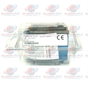


330180-50-05 Bently Nevada 3300 XL Proximitor Transducer
Manufacturer: Bently Nevada
Product No.: 330180-50-05
Condition: In stock
Product Type: Proximitor Sensor
Product Origin: USA
Payment: T/T, Western Union
Weight: 246g
Shipping port: Xiamen
Warranty: 12 months
Estimate delivery times: 12-26 days (International), 3-6 days (United States).
Return within 30 days of purchase. Duties & taxes are non-refundable.
Guaranteed Safe Checkout
330180-50-05 | 3300 XL Proximitor Sensor Engineering Profile
The Bently Nevada 330180-50-05 is a 3300 XL Proximitor Sensor designed for non-contact displacement measurement systems. It interfaces with compatible Bently Nevada proximity probes and extension cables to provide a conditioned output signal for machinery monitoring.
This configuration specifies a 5.0-meter system length, panel mounting, and the CSA, ATEX, and IECEx approval option. Its compact housing supports high-density installation layouts, while SpringLoc terminals simplify field wiring.
The sensor also provides strong radio-frequency and electromagnetic interference immunity. Its isolated mounting base reduces the need for separate isolator plates in suitable installations.
| Product Identification | Details |
|---|---|
| Manufacturer | Bently Nevada |
| Product series | 3300 XL |
| Product type | Proximitor Sensor |
| Complete part number | 330180-50-05 |
| Country of manufacture | U.S.A., according to the supplied product information |
| System length | 5.0 m (16.4 ft) |
| Mounting configuration | Panel mount |
| Agency approval option | CSA, ATEX, IECEx |
| Product condition | New and original, factory packing |
| Warranty | 12 months, subject to confirmed sales terms |
Configuration Breakdown | Decode the Ordering Number
The ordering code identifies the system length, mounting arrangement, and approval selection. Verify the complete code before replacing an installed sensor.
| Code segment | Meaning | Engineering significance |
|---|---|---|
| 330180 | 3300 XL Proximitor Sensor model | Identifies the sensor family and associated transducer interface. |
| -50 | 5.0 m system length with panel mounting | Defines the specified transducer system length and mounting configuration. |
| -05 | CSA, ATEX, IECEx approvals | Identifies the selected approval option for applicable installations. |
Ordering advice: Confirm the existing probe type, extension cable, system length, mounting footprint, and required approvals. Similar-looking sensors may use different electrical characteristics or system configurations.
Technical Specification Matrix
| Parameter | Specification |
|---|---|
| Brand | Bently Nevada |
| Model | 330180-50-05 |
| Series | 3300 XL |
| Device function | Proximitor sensor for a compatible proximity transducer system |
| System length | 5.0 m (16.4 ft) |
| Mounting type | Panel mount |
| Compatible probe families | 3300-series 5 mm probes and 3300 XL 8 mm probes, with compatible extension cables |
| Input supply voltage | −17.5 to −26 VDC under the specified nonincendive circuit conditions |
| Supply requirement with barriers | −23 to −26 VDC |
| Maximum supply current | 12 mA under the specified nonincendive circuit conditions |
| Supply sensitivity | Less than 2 mV output change per 1 V input supply change |
| Output resistance | 50 Ω |
| Sensor housing material | A308 aluminum, as specified in the supplied data |
| Connector material | Gold-plated brass or gold-plated beryllium copper |
| Sensor weight | 246 g (8.67 oz) |
| Operating temperature | −52°C to +100°C (−62°F to +212°F) |
| Storage temperature | −52°C to +105°C (−62°F to +221°F) |
| Mounting base | Provides electrical isolation and supports the specified mounting arrangement |
| Wiring terminals | SpringLoc terminal strips |
| Interference immunity | High RFI/EMI immunity, according to the supplied product description |
Supply voltage caution: The supplied documentation warns that operation above −23.5 VDC can reduce the linear range. Follow the applicable installation drawing and verify the required supply voltage for the actual circuit arrangement.
Signal Conditioning and Electrical Interface
The Proximitor Sensor forms the interface between a compatible proximity probe assembly and the machinery monitoring system. It conditions the probe response and supplies an output for the designated monitor input.
- Probe input: Accepts specified 3300-series 5 mm and 3300 XL 8 mm proximity probes with compatible extension cables.
- Power input: Requires the negative DC supply specified for the installed circuit and barrier arrangement.
- Output interface: Provides the signal required by a compatible machinery monitoring channel.
- Electrical isolation: The mounting base provides isolation under the specified installation arrangement.
- Signal stability: Low supply sensitivity helps limit output changes caused by supply variation within the specified conditions.
- Wiring connection: SpringLoc terminals support tool-free conductor clamping when installed according to the terminal instructions.
Do not assume universal compatibility with PLC analog inputs. Verify the sensor output characteristics, monitor input design, grounding scheme, and required signal conditioning before connecting external equipment.
Installation Architecture and Field Wiring
The panel-mount version shares a four-hole mounting footprint with older Proximitor Sensor designs. Confirm the exact mounting dimensions before using an existing panel layout.
- Inspect the mounting location. Check panel clearance, fastening points, ventilation, and the specified ambient temperature.
- Confirm the system length. Verify the 5.0 m transducer configuration against the complete probe and extension cable arrangement.
- Check the supply circuit. Confirm polarity, negative supply voltage, current capacity, and barrier requirements.
- Prepare the conductors. Follow the applicable wiring drawing and terminal specifications for conductor size and stripping length.
- Connect the wiring. Use the SpringLoc terminals according to the manufacturer's instructions. Check each conductor for secure retention.
- Inspect signal routing. Keep measurement wiring away from major electrical noise sources where practical.
- Verify the channel. Check static output, monitor status, alarm configuration, and signal response before returning equipment to service.
The improved RFI/EMI immunity can support installation in suitable fiberglass housings. It can also reduce reliance on special shielded conduit or metallic housings in appropriate installations. Follow site-specific electrical and hazardous-area requirements.
Typical Equipment and Application Scenarios
| Equipment | Monitoring purpose | Engineering considerations |
|---|---|---|
| Steam turbines | Interface for configured shaft vibration and displacement channels | Match the probe family, system length, and monitoring channel. |
| Gas turbines | Support non-contact shaft measurement within a machinery protection system | Verify installation environment and required approvals. |
| Centrifugal compressors | Provide conditioned proximity signals for shaft condition monitoring | Check probe compatibility and cable configuration. |
| Industrial pumps | Support proximity-based shaft monitoring where the design requires it | Confirm target geometry and the selected probe system. |
| Industrial machinery protection panels | Interface compatible proximity sensors with monitoring electronics | Check power supply, panel footprint, and channel configuration. |
These examples describe potential applications rather than universal machine compatibility. Confirm the installed transducer architecture before selecting a replacement sensor.
Diagnostic Capability and Troubleshooting Workflow
The sensor provides a conditioned measurement signal. The complete monitoring system uses that signal to assess shaft behavior and configured alarm conditions.
| Observed condition | Possible causes | Recommended checks |
|---|---|---|
| Output shifts after a power supply change | Supply voltage outside the preferred range or unstable supply | Measure the supply at the sensor and verify the installation drawing. |
| Channel reports an abnormal gap or displacement value | Probe mismatch, incorrect system length, wiring error, or target changes | Verify the complete transducer chain and compare the static reading with commissioning records. |
| Intermittent signal during operation | Loose conductor, damaged cable, or connector problem | Inspect terminal retention, cable integrity, and connector seating. |
| Signal becomes unstable near switching equipment | Electrical interference or grounding issues | Review cable routing, grounding, and nearby noise sources. |
| Monitor channel remains invalid after replacement | Incorrect model, incompatible probe, wiring mismatch, or channel configuration | Check the part number, input type, wiring drawing, and monitor configuration. |
Field example: A compressor monitoring channel reports a different static reading after a sensor replacement. First, verify the model suffix and system length. Next, measure the supply voltage and inspect the field wiring. Then compare the probe gap and channel configuration with the commissioning records. This sequence helps isolate installation errors before engineers investigate machine damage.
Commissioning and Maintenance Recommendations
- Record baseline values: Document the static output, supply voltage, channel status, and machine operating conditions.
- Inspect terminals: Check SpringLoc conductor retention during scheduled maintenance or after wiring work.
- Verify supply quality: Investigate supply changes before adjusting alarm limits or calibration settings.
- Review cable routing: Check for abrasion, crushed sections, and routing near high-noise equipment.
- Confirm replacement compatibility: Match the full ordering code and probe system before energizing the channel.
- Preserve configuration records: Record monitor settings and transducer details to support future fault isolation.
Certification and Installation Compliance
The -05 ordering suffix identifies the CSA, ATEX, and IECEx approval option in the supplied product information.
Verify the actual certification documents, equipment markings, and installation drawing before use in a hazardous area. Confirm the applicable gas or dust classification, temperature class, and barrier requirements for the intended installation.
Approval selection alone does not establish suitability for every hazardous location. The complete installation must meet the applicable site requirements.
Global PLC Spare HUB's Insight
From a machinery protection perspective, the Proximitor Sensor should be selected as part of a complete transducer system. The sensor, probe, extension cable, power supply, and monitor must work together.
During a planned shutdown, engineers sometimes replace a sensor because its housing and connector appear identical to the installed unit. However, differences in system length or probe compatibility can affect measurement performance. Checking the complete part number before installation reduces this risk.
Another practical consideration involves power supply adjustment. A sensor may operate outside its preferred supply range while producing an apparently usable signal. The supplied specifications warn that a more positive voltage than −23.5 VDC can reduce the linear range. Engineers should verify the required voltage before accepting the measurement channel.
Selection priority: Confirm the system length, mounting configuration, probe compatibility, supply voltage, output interface, and approval requirements. These checks provide a stronger basis for replacement than visual similarity alone.
Model Comparison and Replacement Advice
Compare the current model with the linked alternative before ordering. Both belong to the 3300 XL Proximitor Sensor family, but their complete configurations require verification.
| Selection factor | Current model | Alternative model |
|---|---|---|
| Part number | 330180-50-05 | 330180-92-05 |
| Product family | 3300 XL Proximitor Sensor | 3300 XL series; verify the exact product configuration. |
| System length | 5.0 m (16.4 ft) | Confirm the meaning of option 92 in the applicable ordering documentation. |
| Mounting arrangement | Panel mount | Verify the mounting option before substitution. |
| Approval option | 05 — CSA, ATEX, IECEx | Confirm the approval option and applicable certificates. |
| Replacement suitability | Suitable when the installed system requires this exact configuration | Suitable only when the verified electrical and mechanical configuration matches the application. |
Technical recommendation: Select 330180-50-05 when the installation requires the specified 5.0 m system length, panel mounting, and approval option. Consider the alternative only after confirming its system length, mounting details, electrical characteristics, and certification documents. Do not assume direct interchangeability from the shared 330180 model prefix.
Packaging, Shipping, and Warranty
- Product: Bently Nevada 3300 XL Proximitor Sensor, part number 330180-50-05.
- Condition: New and original, factory packing.
- Warranty: 12 months, subject to confirmed seller terms.
- Shipping carriers: FedEx, UPS, and DHL.
- Availability: Confirm stock and dispatch timing before placing the order.
- Order verification: Confirm the complete part number, mounting option, system length, and approval requirements.
Frequently Asked Questions
1. Why should engineers verify the complete system length instead of the sensor housing alone?
The specified system length relates to the complete transducer arrangement. Incorrect combinations can affect measurement characteristics and calibration. Verify the probe, extension cable, sensor, and applicable system documentation together.
2. What should a technician check before replacing a sensor during a short shutdown?
Record the installed part number, wiring positions, supply voltage, monitor channel settings, and baseline readings. Confirm the replacement configuration before disconnecting the original unit. This preparation reduces commissioning delays and wiring mistakes.
3. Can a standard DC power supply replace the original sensor supply arrangement?
Only if the supply meets the required voltage, polarity, current capacity, isolation, and circuit protection requirements. Hazardous-area installations may require specific barriers. Follow the applicable installation drawing rather than choosing a supply by voltage alone.
4. How can a maintenance team distinguish an electrical fault from a developing machinery problem?
First, verify the sensor supply, wiring, and transducer configuration. Then compare the signal with historical trends and independent machine measurements. A persistent mechanical trend with a verified measurement chain provides stronger diagnostic evidence than one isolated reading.
5. What information helps a supplier confirm the correct replacement model?
Provide the full part number, installed probe model, extension cable configuration, mounting arrangement, supply details, and required hazardous-area approvals. A photograph of the label and the relevant installation drawing can further reduce selection errors.
Request a Quote from Global PLC Spare HUB
Contact Global PLC Spare HUB to request pricing, stock confirmation, and technical selection assistance for the 330180-50-05 Bently Nevada 3300 XL Proximitor Sensor.
Include the existing probe model, system length, mounting arrangement, and required approvals. These details help verify the correct configuration before ordering.
Tags
Q: Are these parts 100% original and new?
A: Yes. Every component is guaranteed to be 100% original, brand-new, and factory-sealed. We also provide a 12-month comprehensive warranty for your peace of mind.
Q: How fast is the shipping to my country?
A: For in-stock items, we offer same-day dispatch. International express shipping (DHL/FedEx/UPS) typically delivers within 3–5 business days worldwide.
Q: Can I get a formal quotation with shipping costs?
A: Absolutely. Our sales team is ready to provide a detailed Proforma Invoice (PI) including the most competitive shipping rates for your location.
Q: Do you offer discounts for bulk orders?
A: We provide volume-based pricing for large projects or multiple-item orders. Please contact us to get our Best Price Guarantee.
12-Month Comprehensive Warranty
Every part supplied by Global PLC Spare Hub is covered by a 12-month warranty from the date of invoice.
- Coverage: Functional defects and hardware failures under normal operating conditions.
- Commitment: We provide immediate repair, replacement, or a full refund for any verified defective components to minimize your operational downtime.
Returns & Exchange Policy
We offer a 30-day return policy to ensure you receive the exact part your system requires.
- Eligibility: Returns are accepted for uninstalled items in their original, factory-sealed packaging.
- RMA Process: Please contact our support team to obtain a Return Merchandise Authorization (RMA) number before shipping.
- Fast Processing: Refunds or exchanges are processed within 3–5 business days after the returned item passes our technical inspection.
Need Technical Assistance?Not sure if this part is compatible with your system? [Consult our Engineers] before purchasing to ensure 100% compatibility.
People Also Bought


