


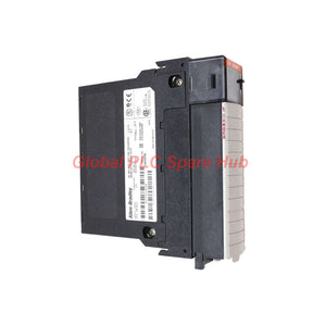

1756-OA16I Allen-Bradley 1756 ControlLogix Isolated AC Digital Output Module
Manufacturer: Allen-Bradley
Product No.: 1756-OA16I
Condition: In stock
Product Type: AC Output Module
Product Origin: USA
Payment: T/T, Western Union
Weight: 420g
Shipping port: Xiamen
Warranty: 12 months
Estimate delivery times: 12-26 days (International), 3-6 days (United States).
Return within 30 days of purchase. Duties & taxes are non-refundable.
Guaranteed Safe Checkout
1756-OA16I Allen-Bradley ControlLogix Isolated AC Output Module
The Allen-Bradley 1756-OA16I is a 16-point discrete AC output module in the ControlLogix 1756 family. It switches external AC loads through individually isolated output points and supports nominal 120 VAC and 240 VAC applications. The specified operating input-to-load voltage range is 74–265 VAC at 47–63 Hz.
For control engineers, the important selection criteria are not limited to channel count. The 1756-OA16I has both per-point and aggregate current limits, temperature-dependent derating, off-state leakage current, and configurable output behavior during program mode and fault conditions. These factors determine whether the module is suitable for contactors, solenoid valves, pilot devices and other AC loads in an existing ControlLogix installation.
01 | Product at a Glance
- Manufacturer: Rockwell Automation
- Brand: Allen-Bradley
- Product family: ControlLogix 1756
- Catalog number: 1756-OA16I
- Module type: Isolated AC digital output module
- Number of outputs: 16 individually isolated points
- Nominal output voltage: 120/240 VAC
- Operating voltage range: 74–265 VAC
- Operating frequency: 47–63 Hz
- Chassis occupancy: Single slot
- Connection method: Removable terminal block (RTB)
- Compatible RTBs listed in the supplied data: 1756-TBCH and 1756-TBS6H
Procurement note: The RTB is a separate compatibility consideration. Confirm whether the required terminal block is included with the offered module and whether the installed wiring assembly is suitable for the replacement.
02 | Output Loading: The Limits Engineers Must Check
The module has separate limits for individual output points and total module current. Meeting the limit on each point does not automatically mean that all 16 outputs can operate at their individual maximum currents simultaneously.
- Continuous current per point at 30 °C: 2 A, with linear derating specified.
- Continuous current per point at 60 °C: 1 A, with linear derating specified.
- Maximum aggregate module current at 30 °C: 5 A, with linear derating specified.
- Maximum aggregate module current at 60 °C: 4 A, with linear derating specified.
- Maximum power dissipation: 5.5 W at 60 °C.
- Thermal dissipation: 18.76 BTU/hr, as listed in the supplied specifications.
Practical example: If several contactors are energized at the same time, calculate their steady-state current and consider the simultaneous operating pattern. Also account for coil inrush, cabinet temperature and the module's aggregate current limit. A design that satisfies the 2 A per-point rating can still exceed the total module rating.
For inductive loads, check the load manufacturer's switching requirements and the applicable Rockwell Automation installation guidance. Do not select a module solely from a contactor's nominal coil voltage.
03 | Switching Characteristics and Electrical Behavior
- OFF-to-ON delay: 9.3 ms at 60 Hz; 11 ms at 50 Hz.
- ON-to-OFF delay: 9.3 ms at 60 Hz; 11 ms at 50 Hz.
- OFF-state leakage current: 3 mA per point.
- ON-state voltage drop: Up to 1.5 V at 2 A; the supplied data lists 6 V at a load current below 50 mA.
- Minimum load current: 10 mA per point, as listed in the supplied specifications.
- Inrush current: 20 A for 43 ms per point, repeatable every 2 seconds at 60 °C, according to the supplied data.
Off-state leakage deserves particular attention when driving low-current loads. A device that receives a small current while the output is logically OFF may glow faintly, remain partially energized or fail to release as expected. Check the load's minimum operating current and leakage tolerance before connecting sensitive electronic loads.
For relay coils, solenoids and contactors, evaluate switching frequency, inrush current and the required suppression method. Confirm that any external suppression component is suitable for the AC load and does not compromise the output's switching behavior.
04 | Output Isolation and Fault-State Configuration
The 1756-OA16I provides individually isolated output points. This arrangement can help separate output circuits, but isolation does not eliminate the need for correct field wiring, branch protection and electrical safety procedures.
- Output behavior during a controller fault: The supplied information lists configurable per-point states of Hold Last State, ON or OFF, with OFF as the default.
- Output behavior during program mode: Hold Last State, ON or OFF are listed as configurable choices, with OFF as the default.
- Internal fusing: The supplied description states that the module has no internal fusing.
- Isolation rating: The supplied material includes conflicting descriptions of the isolation voltage. Confirm the applicable manufacturer's specification for output-to-output and output-to-backplane isolation before using the module in a safety or insulation design.
Choose output fault states according to the machine's risk assessment and process requirements. An OFF command is not a substitute for an independent safety function where hazardous motion, stored energy or process hazards must be controlled.
05 | Backplane, Chassis and Connection Requirements
- Product family: ControlLogix 1756 chassis-based I/O.
- Mounting: One chassis slot.
- Chassis models listed in the supplied material: 1756-A4, 1756-A7, 1756-A10, 1756-A13 and 1756-A17.
- Installation locations: A local rack or a compatible remote I/O rack connected through a suitable 1756 communication adapter.
- RTB options listed: 1756-TBCH and 1756-TBS6H.
- Enclosure style: Open-style module; the installation must provide the required enclosure and environmental protection.
- Operating temperature: 0 to 60 °C, as supplied.
- Humidity: 5–95% non-condensing.
- Maximum operational shock: 30 G, as listed in the supplied data.
Backplane-current discrepancy: The supplied specifications list 225 mA and 300 mA at approximately 5 V, and 2.5 mA and 3 mA at 24 V. These values conflict and should not be combined or treated as verified. Check the official module manual and the chassis power budget before finalizing a replacement or rack design.
The supplied material also lists an output signal schedule time of “16.7s.” Because the unit and meaning are unclear, this value is intentionally excluded from the verified operating characteristics. Confirm it from the applicable technical documentation before using it in a timing calculation.
06 | Suitable Equipment and Industrial Applications
The 1756-OA16I is intended for compatible ControlLogix systems that need to switch AC-powered field devices. Typical applications include:
- Motor control panels: Switching AC control circuits for contactors and motor starter interfaces, subject to load and protection requirements.
- Process skids: Controlling AC solenoid valves, actuators and auxiliary devices.
- Packaging and assembly equipment: Operating AC pilot devices and machine-control loads.
- Water and wastewater plants: Switching compatible AC control loads in pumping and treatment systems.
- HVAC and utility systems: Operating selected AC relays, contactors and auxiliary equipment.
- Industrial furnaces and thermal equipment: Switching suitable AC control loads, provided the load current and control design meet the module's limits.
- ControlLogix maintenance and retrofit projects: Replacing a failed output module while retaining a compatible chassis and field-wiring arrangement.
These are examples of potential applications, not a blanket approval for every device. Verify load voltage, steady-state current, inrush current, switching frequency, leakage tolerance and any required external protection before connecting a field load.
07 | Field Diagnostics: Symptom-Based Checks
Symptom: A field device does not energize
- Confirm the controller is in the intended operating mode and the output command is being issued.
- Check the AC supply voltage and frequency at the field circuit.
- Inspect the terminal-block seating, field wiring, protective devices and load continuity.
- Compare the commanded output state with the module's indicated state and available controller diagnostics.
Symptom: The load remains energized when the output is OFF
- Measure the voltage across the load and account for the specified off-state leakage current.
- Check whether the load has a low input-current requirement or high sensitivity to leakage.
- Inspect for wiring cross-connections or an unintended alternate supply path.
- Do not assume a logically OFF output provides galvanic disconnection from the AC supply.
Symptom: The module or field circuit trips under simultaneous operation
- Measure the current of individual loads and calculate the aggregate current.
- Check both the per-point limit and the total module limit at the actual cabinet temperature.
- Review coil inrush, load switching frequency, branch protection and external suppression.
- Determine whether the problem follows a particular load or occurs only when multiple outputs are active.
Symptom: Output behavior changes after a controller fault or mode change
- Review the configured fault state and program-mode state for the affected output points.
- Confirm whether Hold Last State, ON or OFF is configured.
- Check controller status and event history before replacing the module.
- Validate the expected restart sequence and ensure that field devices return to a safe operating condition.
Symptom: A replacement module does not operate as expected
- Verify the exact catalog number and the module's physical condition.
- Confirm the chassis, terminal block and wiring arrangement are compatible.
- Check the project configuration and output addressing against the installed hardware.
- Review the fault-state settings and confirm that the field supply is within the specified AC range.
Always isolate and verify the absence of hazardous voltage before touching field wiring. AC output circuits can remain energized independently of the controller's logic state.
08 | Global PLC Spare HUB's Insight
For the 1756-OA16I, output-current calculations and field-load behavior are often more useful than the channel count alone when planning a replacement. The 16 isolated points provide flexibility for multiple AC circuits, but the aggregate current limit means that the total load must be assessed alongside the current on each individual point.
In troubleshooting, separate a control-logic problem from a field-power problem. If the output command changes correctly but the load does not respond, inspect the AC supply, RTB connections, load continuity and protection devices before concluding that the output electronics have failed. If the load remains partially energized with the output OFF, investigate leakage current and the load's minimum operating current.
Before ordering a spare, provide the full catalog number, a label photo, the existing terminal-block model and the type of AC loads being controlled. For critical equipment, also record the controller fault-state requirements and the cabinet operating temperature. This information helps establish whether the replacement is appropriate for the installed application.
09 | Warranty and Shipping
- Warranty: 12 months, subject to the agreed sales terms.
- Pre-shipment checks: Model identification and condition checks, as applicable to the supplied unit.
- Courier options: FedEx, UPS and DHL, subject to destination and service availability.
- Quotation: Contact Global PLC Spare HUB with the quantity, delivery destination and compatibility details to request pricing and lead-time information.
10 | Frequently Asked Questions
Q1: Can the 1756-OA16I switch a 240 VAC load if the nominal voltage is listed as 120/240 VAC?
The supplied operating range is 74–265 VAC at 47–63 Hz, which includes nominal 240 VAC. Confirm the actual load current, inrush characteristics, circuit protection and the manufacturer's installation requirements before connecting the device. The voltage range alone does not establish that every 240 VAC load is suitable.
Q2: How do I determine whether the module's total current rating is sufficient for my machine?
List the steady-state current of each connected load, identify which loads can operate simultaneously and calculate the aggregate demand. Check the current limit for every point as well as the module-wide limit. Repeat the assessment at the expected cabinet temperature because the supplied current ratings are lower at 60 °C than at 30 °C.
Q3: Is the 1756-OA16I suitable for directly driving a small electronic input that draws very little current?
Do not decide from the voltage rating alone. The supplied data lists 3 mA of off-state leakage per point and a minimum sustained load current of 10 mA. Compare these values with the connected device's input specifications. For a sensitive or low-current load, verify compatibility with the manufacturer's documentation and consider an appropriate interface device if required.
Q4: What should I check before transferring the existing terminal block to a replacement module?
Confirm the terminal block model, wiring condition, terminal integrity and compatibility with the replacement. Record wire labels and verify each circuit against the electrical drawings before disconnecting anything. Follow site lockout procedures and verify that hazardous AC voltage is absent before handling the RTB or field conductors.
Q5: What information helps avoid ordering the wrong ControlLogix output module?
Provide the complete catalog number, a photo of the installed label, the chassis and RTB details, the field voltage, the connected load types and the required fault-state behavior. If the module is part of a legacy installation, include the controller and project configuration details where available. Similar-looking output modules may differ in isolation, load type, current limits and wiring requirements, so verify the exact model rather than selecting by appearance alone.
Tags
Q: Are these parts 100% original and new?
A: Yes. Every component is guaranteed to be 100% original, brand-new, and factory-sealed. We also provide a 12-month comprehensive warranty for your peace of mind.
Q: How fast is the shipping to my country?
A: For in-stock items, we offer same-day dispatch. International express shipping (DHL/FedEx/UPS) typically delivers within 3–5 business days worldwide.
Q: Can I get a formal quotation with shipping costs?
A: Absolutely. Our sales team is ready to provide a detailed Proforma Invoice (PI) including the most competitive shipping rates for your location.
Q: Do you offer discounts for bulk orders?
A: We provide volume-based pricing for large projects or multiple-item orders. Please contact us to get our Best Price Guarantee.
12-Month Comprehensive Warranty
Every part supplied by Global PLC Spare Hub is covered by a 12-month warranty from the date of invoice.
- Coverage: Functional defects and hardware failures under normal operating conditions.
- Commitment: We provide immediate repair, replacement, or a full refund for any verified defective components to minimize your operational downtime.
Returns & Exchange Policy
We offer a 30-day return policy to ensure you receive the exact part your system requires.
- Eligibility: Returns are accepted for uninstalled items in their original, factory-sealed packaging.
- RMA Process: Please contact our support team to obtain a Return Merchandise Authorization (RMA) number before shipping.
- Fast Processing: Refunds or exchanges are processed within 3–5 business days after the returned item passes our technical inspection.
Need Technical Assistance?Not sure if this part is compatible with your system? [Consult our Engineers] before purchasing to ensure 100% compatibility.
People Also Bought


