


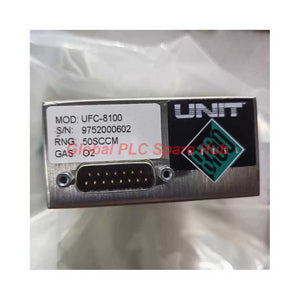
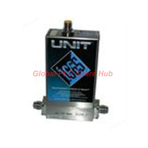
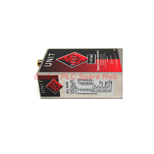
UFC-8100 UNIT Instruments Analog Mass Flow Controller 8100 Series
Manufacturer: UNIT Instruments
Product No.: UFC-8100
Condition: In stock
Product Type: Mass Flow Controller
Product Origin: USA
Payment: T/T, Western Union
Weight: 500g
Shipping port: Xiamen
Warranty: 12 months
Estimate delivery times: 12-26 days (International), 3-6 days (United States).
Return within 30 days of purchase. Duties & taxes are non-refundable.
Guaranteed Safe Checkout
UFC-8100 | UNIT Instruments High-Flow Analog Mass Flow Controller
The UNIT Instruments UFC-8100 is an elastomer-sealed analog mass flow controller designed for high-flow process gas applications. It belongs to the 8100 Series and supports nitrogen-equivalent flow ranges from 3 sccm to 30 slm.
The controller combines a proportional electromagnetic control valve, precision flow measurement, and a 0–5 VDC analog interface. Its design supports non-corrosive semiconductor gases and general industrial gas delivery systems.
With a maximum operating pressure of 3,500 kPa (500 psi), the UFC-8100 addresses applications that require higher pressure capability than many conventional analog MFC configurations. Its fast-start response, low-flow control range, and elastomer-sealed construction also make it a candidate for selected analog MFC replacement projects.
ENGINEERING PROFILE | Key Specifications
| Specification | Value |
|---|---|
| Manufacturer | UNIT Instruments |
| Model | UFC-8100 |
| Product Series | 8100 Series |
| Product Type | High-Flow Analog Mass Flow Controller |
| Seal Design | Elastomer Seal |
| Full-Scale Flow Range | 3 sccm to 30 slm, N2 equivalent |
| Analog Accuracy | ±1% FS; ±0.35% FS below 35% FS |
| Repeatability | ±0.15% FS, per SEMI E56-96 |
| Linearity | ±0.5% FS, per SEMI E27-92 |
| Control Range | 2–100% FS |
| Fast-Start Response | ≤1.0 second, per SEMI E17-91 |
| Soft-Start Function | Linear ramp at 20% per second; 0–100% in 5 seconds |
| Zero Stability | ≤0.6% FS per year without auto-zero |
| Operating Temperature | 0–50°C (32–122°F) |
| Heating Configuration | Standard unheated version |
| MTBF | 536,000 hours, as specified |
| Certification | CE certified; specified SEMI compliance |
01 / FLOW CONTROL PERFORMANCE
The UFC-8100 provides a 2–100% FS control range. This allows the controller to regulate flow from low operating points through its rated full-scale range.
- Fast response: The specified fast-start response is no more than 1.0 second under the referenced SEMI test method.
- Controlled ramping: Soft start increases the setpoint at 20% FS per second, reaching 100% in five seconds.
- Measurement consistency: Repeatability is specified at ±0.15% FS.
- Flow accuracy: The analog model specifies ±1% FS overall and ±0.35% FS below 35% FS.
- Long-term stability: Zero stability is specified at ≤0.6% FS per year without auto-zero.
Engineering interpretation: Accuracy, repeatability, and linearity describe different performance characteristics. They should not be treated as interchangeable values when assessing process tolerance.
02 / PRESSURE AND GAS-PATH DESIGN
| Parameter | Specification |
|---|---|
| Maximum Operating Pressure | 3,500 kPa (500 psi) |
| Proof Pressure | 10,500 kPa (1,500 psi) |
| Differential Pressure | 6.65–350 kPa (50 torr–50 psid) |
| Wetted Materials | 316L stainless steel, K-M45, 304 stainless steel, and 7Mo+ |
| Surface Finish | 32 micro-inch Ra |
| Elastomer Seals | Viton or Neoprene O-rings |
| Valve Seat Options | Kel-F or metal seat |
| Helium Leak Integrity | 1 × 10⁻⁹ atm·cc/sec, per SEMI E16-90 |
The gas-contact construction combines stainless steel components with elastomer sealing elements. The specified surface finish supports process gas path requirements, while the selected seal and valve seat determine application compatibility.
The proof-pressure rating is a pressure qualification value, not a normal operating target. Do not operate the controller continuously at proof pressure.
03 / ANALOG INTERFACE AND VALVE OPERATION
The standard UFC-8100 configuration uses an analog electrical interface. It connects to the host equipment through a 20-pin card edge connector.
| Electrical Item | Specification |
|---|---|
| Setpoint Signal | 0–5 VDC |
| Monitor Signal | 0–5 VDC |
| Connector | 20-pin card edge connector |
| Positive Supply | +15 VDC, 100 mA maximum |
| Negative Supply | −15 VDC, 200 mA maximum |
| Maximum Power Consumption | 4.5 W |
| Control Valve | Proportional electromagnetic UNIT 132 valve |
| Valve Configuration | Normally closed or normally open, depending on configuration |
The proportional electromagnetic valve regulates gas flow in response to the analog control signal. The selected valve configuration determines its behavior when electrical power is removed.
Before connecting the controller, verify the 20-pin connector assignment, signal common, supply polarity, and host equipment input/output scaling. Do not assume pin compatibility with another manufacturer's analog MFC.
04 / TEMPERATURE AND PRESSURE SENSITIVITY
| Characteristic | Specified Value |
|---|---|
| Zero Temperature Coefficient | 0.05% FS/°C |
| Span Temperature Coefficient | 0.1% FS/°C |
| Pressure Coefficient | 0.007% of reading per psi, N2 |
| Operating Temperature | 0–50°C |
Temperature changes can affect zero and span performance. Pressure changes can also influence the indicated flow. For critical processes, maintain stable operating conditions and evaluate calibration performance under representative process pressure and temperature.
05 / MECHANICAL CONFIGURATION
| Mechanical Parameter | Value |
|---|---|
| Approximate Dimensions (H × W × D) | 137 × 127 × 38 mm |
| Footprint | Approximately 1.5 inches |
| 1/4 VCR Overall Length | 124 mm |
| Weight | 1.2 kg (2.65 lb) |
| Standard Heating | Unheated |
Check the actual dimensional drawing before installation. The stated overall dimensions and 1/4 VCR length refer to different dimensional references and should not be substituted for a port-to-port drawing.
06 / PROCESS APPLICATIONS
The 8100 Series is designed for non-corrosive process gas control. Typical applications include:
- Semiconductor gas delivery: Nitrogen, argon, helium, oxygen, hydrogen, and other compatible process gases.
- Deposition equipment: Gas supply control for selected CVD and PVD processes.
- Etching systems: Flow regulation for compatible non-corrosive process gases.
- General process gas control: Analog flow regulation in industrial gas systems.
- Equipment upgrades: Replacement of selected elastomer-sealed analog mass flow controllers.
Gas compatibility must be checked against the actual wetted materials, seal compound, valve seat, and gas purity requirements. The general gas list does not establish universal compatibility with every configuration.
07 / REPLACEMENT ENGINEERING CHECKPOINTS
The manufacturer describes the UFC-8100 as a drop-in replacement candidate for elastomeric MFCs. However, a reliable replacement requires more than matching the flow range.
- Flow calibration: Confirm nitrogen-equivalent full scale and the calibration gas used by the existing controller.
- Mechanical interface: Compare fitting type, port orientation, footprint, and overall length.
- Electrical connection: Check the 20-pin card edge connector and every relevant pin assignment.
- Signal scaling: Confirm 0–5 VDC setpoint and monitor compatibility with the equipment controller.
- Pressure conditions: Verify operating pressure and available differential pressure at actual process flow.
- Gas-path materials: Confirm the elastomer, valve seat, and metal materials are suitable for the process gas.
- Valve fail position: Select the correct normally-open or normally-closed configuration for the process shutdown strategy.
For replacement projects, obtain the existing MFC model number, gas type, full-scale range, connector information, and fitting details. These details help establish whether the proposed replacement is electrically and mechanically compatible.
08 / INSTALLATION AND MAINTENANCE GUIDANCE
- Install the controller in a clean gas line with suitable upstream filtration.
- Use compatible fittings and follow the specified connection manufacturer's assembly procedure.
- Avoid applying mechanical stress to the body or gas connections during installation.
- Confirm that process pressure remains within the operating limits.
- Verify both DC supply rails before applying the analog command.
- Allow the equipment to stabilize before checking zero and flow performance.
- Investigate zero drift, unstable output, and slow response before replacing the unit.
Common diagnostic checks include gas supply pressure, line restrictions, connector integrity, power stability, analog signal scaling, and gas calibration. For a persistent deviation, compare measured flow with a calibrated reference instrument under controlled conditions.
09 / COMPLIANCE AND CALIBRATION
- CE: CE certified, according to the supplied product information.
- SEMI E12: Specified compliance.
- SEMI E16-90: Referenced for helium leak integrity.
- SEMI E17-91: Referenced for fast-start response.
- SEMI E27-92: Referenced for linearity.
- SEMI E56-96: Referenced for repeatability.
- Calibration: NIST-traceable calibration.
SEMI references identify the stated performance or compliance basis. Confirm the applicable revision, test report, and certification documents when project specifications require formal evidence.
10 / SUPPLY AND COMMERCIAL INFORMATION
| Supply Item | Details |
|---|---|
| Product | UNIT Instruments UFC-8100 |
| Product Condition | New & Original in Factory Packing |
| Warranty | Factory Warranty: 12 Months |
| Shipping | FedEx, UPS, DHL |
| Technical Confirmation | Model and configuration verification available upon inquiry |
Contact Global PLC Spare HUB for pricing, stock availability, and configuration confirmation. Please provide the required flow range, process gas, fitting type, and valve action when requesting a quotation.
GLOBAL PLC SPARE HUB | APPLICATION ENGINEERING NOTES
One important selection issue is the difference between full-scale accuracy and low-range accuracy. The stated analog accuracy is ±1% FS, while the specification also lists ±0.35% FS below 35% FS. Engineers should confirm the manufacturer's exact measurement basis and operating conditions before using the tighter figure in a process tolerance calculation.
For a 30 slm full-scale model, ±1% FS corresponds to ±0.3 slm. The 2% FS lower control boundary corresponds to 0.6 slm. These values help determine whether the selected range can meet both the process minimum and maximum flow requirements.
The high pressure rating also requires careful interpretation. The 500 psi maximum operating pressure does not remove the need for adequate differential pressure across the controller. A system can have high inlet pressure and still fail to provide the differential pressure required for the requested flow.
Finally, the 536,000-hour MTBF figure should be treated as a specified reliability value, not a guaranteed service life. Actual operating life depends on gas cleanliness, pressure cycling, valve duty, temperature, and maintenance conditions.
FREQUENTLY ASKED QUESTIONS
Q1. What is the practical difference between fast start and soft start?
Fast start prioritizes reaching a new flow target quickly. Soft start deliberately limits the rate of increase to reduce abrupt gas delivery changes. Select the mode according to chamber process requirements, downstream pressure sensitivity, and equipment sequencing.
Q2. Does the 500 psi pressure rating mean the controller can deliver its full rated flow at 500 psi?
No. Maximum operating pressure and available differential pressure are separate conditions. Actual flow capability depends on the pressure drop across the controller, gas properties, and selected full-scale configuration. Check the operating pressure curve for the intended gas and flow.
Q3. How should I evaluate the 0.15% FS repeatability specification?
Repeatability describes how consistently the unit returns to the same flow under comparable conditions. It does not mean the absolute flow reading is accurate to 0.15%. For process validation, evaluate repeatability together with accuracy, linearity, and calibration uncertainty.
Q4. What information is needed to confirm an analog replacement for an existing MFC?
Provide the existing model, gas type, full-scale flow, analog signal range, connector pinout, fitting configuration, supply voltage, and valve fail position. A dimensional drawing and equipment wiring diagram are especially useful when the replacement must fit an existing gas panel.
Q5. When should I request a new calibration or performance check?
Consider verification after extended storage, gas-line contamination, major pressure changes, unexplained zero drift, or repeated process-flow deviations. For critical semiconductor processes, follow the equipment maintenance schedule and acceptance criteria rather than relying only on the annual zero-stability specification.
Tags
Q: Are these parts 100% original and new?
A: Yes. Every component is guaranteed to be 100% original, brand-new, and factory-sealed. We also provide a 12-month comprehensive warranty for your peace of mind.
Q: How fast is the shipping to my country?
A: For in-stock items, we offer same-day dispatch. International express shipping (DHL/FedEx/UPS) typically delivers within 3–5 business days worldwide.
Q: Can I get a formal quotation with shipping costs?
A: Absolutely. Our sales team is ready to provide a detailed Proforma Invoice (PI) including the most competitive shipping rates for your location.
Q: Do you offer discounts for bulk orders?
A: We provide volume-based pricing for large projects or multiple-item orders. Please contact us to get our Best Price Guarantee.
12-Month Comprehensive Warranty
Every part supplied by Global PLC Spare Hub is covered by a 12-month warranty from the date of invoice.
- Coverage: Functional defects and hardware failures under normal operating conditions.
- Commitment: We provide immediate repair, replacement, or a full refund for any verified defective components to minimize your operational downtime.
Returns & Exchange Policy
We offer a 30-day return policy to ensure you receive the exact part your system requires.
- Eligibility: Returns are accepted for uninstalled items in their original, factory-sealed packaging.
- RMA Process: Please contact our support team to obtain a Return Merchandise Authorization (RMA) number before shipping.
- Fast Processing: Refunds or exchanges are processed within 3–5 business days after the returned item passes our technical inspection.
Need Technical Assistance?Not sure if this part is compatible with your system? [Consult our Engineers] before purchasing to ensure 100% compatibility.
People Also Bought


