


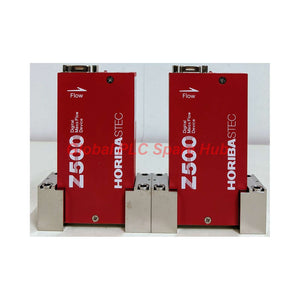
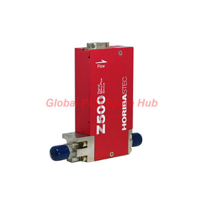
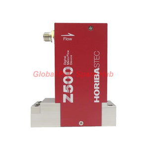
SEC-Z524 HORIBA STEC Mass Flow Controller | SEC-Z500X DeviceNet Series
Manufacturer: HORIBA
Product No.: SEC-Z524
Condition: In stock
Product Type: Mass Flow Controller
Product Origin: USA
Payment: T/T, Western Union
Weight: 500g
Shipping port: Xiamen
Warranty: 12 months
Estimate delivery times: 12-26 days (International), 3-6 days (United States).
Return within 30 days of purchase. Duties & taxes are non-refundable.
Guaranteed Safe Checkout
Product Overview | Semiconductor Gas Flow Control
SEC-Z524 is a DeviceNet-compatible mass flow controller manufactured by HORIBA STEC. It belongs to the SEC-Z500X Series and supports medium-to-high flow gas delivery applications.
This model provides a full-scale flow range of 22 to 50 SLM, based on nitrogen equivalent specifications. Its thermal mass flow control architecture supports precise gas delivery in semiconductor manufacturing equipment.
The integrated piezoelectric actuator regulates gas flow through an electronically controlled valve. DeviceNet communication connects the controller to compatible automation networks.
Its multi-gas and multi-range configuration supports different process gas requirements. The extended 124 mm fitting distance also provides an important mechanical reference for gas panel integration.
Typical applications include CVD systems, plasma etching equipment, and semiconductor bulk gas delivery panels. Engineers can select the appropriate configuration according to gas properties, operating pressure, flow range, and connection requirements.
Product Identification & Engineering Specifications
| Manufacturer | HORIBA STEC |
| Model | SEC-Z524 |
| Product Series | SEC-Z500X |
| Communication Version | DeviceNet |
| Product Type | Mass Flow Controller (MFC) |
| Flow Classification | Medium-Flow MFC |
| Full-Scale Flow Range | 22–50 SLM |
| Reference Gas | Nitrogen Equivalent (N2) |
| Range Configuration | MR/MG #6.5–#08 |
| Control Range | 2–100% FS |
| Valve Technology | Piezoelectric Actuator |
| Valve Configuration | Normally Open or Normally Closed |
| Heating Configuration | Standard Unheated Version |
| Power Supply | 24 VDC |
| Power Consumption | 4.0 VA |
| Electrical Connector | Micro-Connector |
| Wetted Materials | SUS316L Stainless Steel |
| Internal Surface | Standard Polished Finish |
| Seal Options | Metal or Elastomer |
| Fitting Connection | 1/4-inch VCR |
| Fitting Distance | 124 mm |
| Overall Dimensions | 126 × 64 × 29 mm (H × W × T) |
01 | Flow Measurement and Control Performance
The controller regulates gas delivery across a specified 2–100% full-scale operating range. Its accuracy specifications use different reference conditions above and below 25% of full scale.
| Performance Parameter | Specification |
| Full-Scale Flow | 22–50 SLM |
| Control Range | 2–100% FS |
| Accuracy Above 25% FS | ±1.0% S.P. |
| Accuracy at or Below 25% FS | ±0.25% FS |
| Repeatability | ±0.2% FS |
| Linearity | ±0.5% FS |
| Response Time | ≤1 second (T98, full flow range) |
Measurement Interpretation:
- Accuracy: Describes flow measurement deviation under the specified reference conditions.
- Repeatability: Indicates consistency across repeated measurements.
- Linearity: Describes deviation from the specified linear response.
- Response Time: T98 represents the time required to reach 98% of the final flow response.
- Control Range: Defines the specified operating span relative to full-scale flow.
Engineers should use the appropriate accuracy equation for each operating region. Do not treat percentage of setpoint and percentage of full scale as interchangeable values.
02 | Multi-Gas Compatibility and Process Selection
The SEC-Z524 supports multi-gas configurations for semiconductor gas delivery systems. Its listed gas applications include:
| Gas Category | Specified Gas Examples |
| Inert Gases | N2, Ar, He |
| Reactive Gases | H2 |
| Specialty Gases | SF6, HBr, WF6 |
Additional gas configurations may be available according to the selected calibration and wetted-material requirements.
Gas Selection Considerations:
- Confirm the exact gas composition before ordering.
- Verify the gas-specific calibration and full-scale range.
- Consider gas density, thermal properties, and operating conditions.
- Check chemical compatibility with SUS316L and the selected seals.
- Confirm process cleanliness requirements for semiconductor applications.
Important: Nitrogen-equivalent flow ratings do not automatically represent identical actual flow rates for other gases. Use the correct gas calibration and conversion data for process calculations.
03 | DeviceNet Communication and Electrical Integration
The SEC-Z500X DeviceNet configuration supports communication with compatible industrial automation networks.
| Communication Parameter | Specification |
| Network Protocol | DeviceNet |
| Conformance | ODVA Conformant |
| Baud Rate | 125 / 250 / 500 kbps |
| Electrical Connector | Micro-Connector |
| Supply Voltage | 24 VDC |
| Power Consumption | 4.0 VA |
Network Integration Checklist:
- Confirm the DeviceNet master supports the required device profile.
- Set the network baud rate to match the existing bus configuration.
- Configure the correct node address and communication parameters.
- Verify the DeviceNet cable and connector pin assignments.
- Check the 24 VDC supply before network commissioning.
- Verify device communication and process data exchange.
ODVA conformance supports integration with compatible DeviceNet equipment. Confirm the controller configuration and available device description files before commissioning.
04 | Pressure Conditions and Gas Circuit Integrity
Stable pressure conditions are essential for repeatable flow regulation. Engineers should evaluate differential pressure and maximum operating pressure separately.
| Pressure Parameter | Specification |
| Operating Differential Pressure | 200–300 kPa(d) |
| Maximum Operating Pressure | 450 kPa(g) |
| Pressure Resistance | 1000 kPa(g) |
| Helium Leak Integrity | ≤5 × 10⁻¹² Pa·m³/s |
Process Engineering Notes:
- Maintain the specified operating differential pressure.
- Check upstream supply pressure stability.
- Evaluate downstream pressure and exhaust conditions.
- Prevent pressure fluctuations during flow calibration.
- Verify gas line cleanliness before installation.
- Confirm leak integrity after gas connection work.
The specified helium leak rate provides an important reference for gas circuit integrity. Follow the approved leak-testing procedure for the complete installation.
05 | Wetted Materials, Seals and Mechanical Connections
The gas-contacting construction uses SUS316L stainless steel with a polished internal surface as standard. Seal selection depends on the process gas and chemical compatibility requirements.
| Component | Construction |
| Wetted Body | SUS316L Stainless Steel |
| Internal Surface | Polished Standard Finish |
| Seal Options | Metal or Elastomer |
| Gas Connection | 1/4-inch VCR |
| Fitting Distance | 124 mm |
| Overall Dimensions | 126 × 64 × 29 mm |
Mechanical Installation Considerations:
- Check the 124 mm fitting distance against the gas panel layout.
- Verify the 1/4-inch VCR connection specification.
- Select seals according to gas compatibility requirements.
- Prevent particle contamination during connection work.
- Avoid excessive mechanical stress on the fitting interfaces.
- Follow the applicable VCR assembly and tightening procedure.
The extended fitting distance is an important selection dimension. Confirm the actual mating connection geometry before modifying an existing gas panel.
06 | Temperature and Installation Environment
| Environmental Parameter | Specification |
| Operating Temperature | 5°C to 50°C |
| Recommended Temperature | 15°C to 45°C |
| Heating Configuration | Unheated Standard Version |
The standard configuration does not include a heating option. Maintain the recommended ambient temperature when process stability is important.
Installation Recommendations:
- Verify the installation location and available mounting space.
- Confirm gas compatibility and selected flow range.
- Inspect the internal gas circuit and connection surfaces.
- Install the VCR fittings using approved procedures.
- Connect the 24 VDC supply and DeviceNet interface.
- Check the network configuration before enabling process flow.
- Perform leak testing before introducing process gases.
- Verify flow response under the specified pressure conditions.
07 | Valve Control and Functional Configuration
The controller uses a piezoelectric actuator for valve operation. The specified configuration allows normally open or normally closed valve arrangements.
- Actuator Technology: Piezoelectric.
- Valve Options: Normally Open or Normally Closed.
- Control Function: Electronic regulation of gas flow.
- Heating: Not included in the standard configuration.
Selection Advice: Confirm the required valve configuration before ordering. Normally open and normally closed arrangements can produce different process responses during power loss or system shutdown.
Do not assume the valve's fail position without checking the exact model configuration and manufacturer's documentation.
08 | Commissioning, Calibration and Maintenance
Proper commissioning establishes a reliable baseline for semiconductor gas delivery. Verify electrical, mechanical, pneumatic, and communication conditions before production operation.
Commissioning Procedure:
- Confirm the complete model and gas calibration configuration.
- Verify supply voltage and electrical connector wiring.
- Check DeviceNet node configuration and baud rate.
- Confirm the operating pressure differential.
- Perform helium leak testing where required.
- Check zero-flow behavior before applying flow commands.
- Compare indicated flow with the specified reference conditions.
- Record operating pressure and flow performance.
Maintenance Recommendations:
- Monitor zero-flow stability during routine operation.
- Investigate unexpected deviations from established flow readings.
- Inspect gas connections for leakage after maintenance.
- Check network communication for intermittent faults.
- Review gas purity and upstream filtration conditions.
- Verify seal compatibility when changing process gases.
- Follow HORIBA STEC service procedures for internal maintenance.
Calibration intervals should follow the process accuracy requirements and equipment maintenance plan. Do not change calibration parameters without the correct gas-specific reference data.
09 | Compliance and Industry Applications
The supplied specifications identify the following compliance and integration references:
- RoHS: RoHS compliant.
- DeviceNet: ODVA conformance.
- SEMI: SEMI standards compliance as specified.
Typical Industrial Applications:
- CVD Equipment: Controlled gas delivery for chemical vapor deposition processes.
- Etching Systems: Gas flow regulation in semiconductor etch equipment.
- Bulk Gas Panels: Medium-flow gas supply and distribution.
- Gas Cabinets: Automated specialty gas delivery systems.
- Semiconductor Manufacturing: DeviceNet-based process gas control.
Verify the exact applicable SEMI requirements and compliance documentation for the intended equipment installation.
10 | Compatibility and Purchasing Verification
Before selecting SEC-Z524, engineers should verify the following configuration details.
| Selection Item | Verification Requirement |
| Model | SEC-Z524 |
| Series | SEC-Z500X DeviceNet |
| Flow Range | 22–50 SLM, N2 equivalent |
| Gas Calibration | Match the actual process gas |
| Range Code | Confirm MR/MG #6.5–#08 configuration |
| Communication | DeviceNet protocol |
| Baud Rate | 125 / 250 / 500 kbps |
| Pressure | Confirm operating differential pressure |
| Seal Material | Metal or elastomer, according to gas compatibility |
| Valve Configuration | Normally open or normally closed |
| Connection | 1/4-inch VCR, 124 mm fitting distance |
Replacement Considerations:
- Do not substitute based on flow range alone.
- Match the actual gas calibration and range configuration.
- Verify DeviceNet communication compatibility.
- Check valve configuration and power requirements.
- Confirm mechanical connection dimensions.
- Review wetted materials and seal compatibility.
Two controllers with identical nominal flow ranges may have different gas calibrations, valve configurations, and electrical interfaces. Verify the complete ordering configuration before replacement.
11 | Packaging and Supply Information
| Item | Description |
| Manufacturer | HORIBA STEC |
| Model | SEC-Z524 |
| Series | SEC-Z500X DeviceNet |
| Product Type | Mass Flow Controller |
| Supply Quantity | 1 Unit |
| Accessories | Confirm separately with supplier |
Confirm the gas calibration, fitting configuration, valve arrangement, and supplied accessories before placing an order.
Frequently Asked Questions
Q1: Can engineers transfer an existing gas calibration from another MFC to this controller?
Not automatically. Gas calibration depends on the controller configuration and reference conditions. Verify the specified gas, range code, and calibration data. Never assume identical flow readings across different gas configurations.
Q2: What can cause unstable readings when the gas supply remains constant?
Potential causes include upstream pressure fluctuations, gas contamination, temperature variation, incorrect gas selection, and unstable downstream conditions. Compare actual pressure measurements with the commissioning baseline before changing controller settings.
Q3: How should engineers evaluate a controller installed in a high-purity gas system?
Review wetted materials, seal compatibility, internal surface finish, and leak integrity. Also assess gas purity, connection cleanliness, and contamination risks during installation. Follow the facility's semiconductor gas handling procedures.
Q4: What should technicians check when DeviceNet communication works but flow commands produce unexpected results?
Check the configured gas range, engineering units, process data mapping, and flow command scaling. Then verify the physical gas supply and differential pressure. Network communication alone does not confirm correct process configuration.
Q5: How should buyers choose between normally open and normally closed valve configurations?
Evaluate the required gas isolation strategy during power loss, shutdown, and emergency conditions. Review the system safety design and the consequences of each valve position. Confirm the exact actuator configuration before purchasing.
Tags
Q: Are these parts 100% original and new?
A: Yes. Every component is guaranteed to be 100% original, brand-new, and factory-sealed. We also provide a 12-month comprehensive warranty for your peace of mind.
Q: How fast is the shipping to my country?
A: For in-stock items, we offer same-day dispatch. International express shipping (DHL/FedEx/UPS) typically delivers within 3–5 business days worldwide.
Q: Can I get a formal quotation with shipping costs?
A: Absolutely. Our sales team is ready to provide a detailed Proforma Invoice (PI) including the most competitive shipping rates for your location.
Q: Do you offer discounts for bulk orders?
A: We provide volume-based pricing for large projects or multiple-item orders. Please contact us to get our Best Price Guarantee.
12-Month Comprehensive Warranty
Every part supplied by Global PLC Spare Hub is covered by a 12-month warranty from the date of invoice.
- Coverage: Functional defects and hardware failures under normal operating conditions.
- Commitment: We provide immediate repair, replacement, or a full refund for any verified defective components to minimize your operational downtime.
Returns & Exchange Policy
We offer a 30-day return policy to ensure you receive the exact part your system requires.
- Eligibility: Returns are accepted for uninstalled items in their original, factory-sealed packaging.
- RMA Process: Please contact our support team to obtain a Return Merchandise Authorization (RMA) number before shipping.
- Fast Processing: Refunds or exchanges are processed within 3–5 business days after the returned item passes our technical inspection.
Need Technical Assistance?Not sure if this part is compatible with your system? [Consult our Engineers] before purchasing to ensure 100% compatibility.
People Also Bought


