


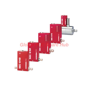
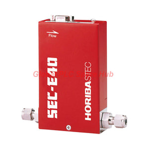
SEC-E431X SEC-E Series HORIBA STEC High-Flow Gas Controller
Manufacturer: HORIBA
Product No.: SEC-E431X
Condition: In stock
Product Type: Gas Controller
Product Origin: USA
Payment: T/T, Western Union
Weight: 500g
Shipping port: Xiamen
Warranty: 12 months
Estimate delivery times: 12-26 days (International), 3-6 days (United States).
Return within 30 days of purchase. Duties & taxes are non-refundable.
Guaranteed Safe Checkout
SEC-E431X | High-Flow Economy Gas Control Solution
The SEC-E431X is an economy-type Mass Flow Controller from the HORIBA STEC SEC-E Series. It uses a solenoid valve to regulate high-flow delivery of non-corrosive process gases.
Its nitrogen-equivalent full-scale flow range covers 50 to 100 SLM. This configuration addresses gas distribution requirements in bulk gas panels and industrial process equipment.
The controller combines analog voltage control with a normally closed solenoid valve. Its standard unheated construction simplifies integration into compatible gas delivery assemblies. The design emphasizes practical flow regulation, straightforward electrical connections, and economical system configuration.
01 | Product Configuration at a Glance
| Identification | Specification |
| Manufacturer | HORIBA STEC |
| Model | SEC-E431X |
| Product Series | SEC-E Economy Solenoid Valve |
| Product Type | Mass Flow Controller (MFC) |
| Full-Scale Flow Range | 50–100 SLM |
| Flow Reference Gas | Nitrogen equivalent |
| Gas Compatibility | Non-corrosive gases |
| Heating Configuration | Standard unheated version |
| Valve Technology | Solenoid valve |
| Valve State Without Power | Normally closed |
| Process Connection | 3/8-inch Swagelok |
02 | Flow Regulation and Measurement Performance
The SEC-E431X provides a 5–100% FS control range. Its accuracy and repeatability specifications define the expected flow regulation performance.
| Performance Parameter | Specification |
| Accuracy | ±1% FS |
| Repeatability | ±0.5% FS |
| Linearity | ±0.5% FS |
| Response Time | ≤1 second, T98 typical |
| Control Range | 5–100% FS |
| Full-Scale Flow | 50–100 SLM |
Engineering Note: Accuracy and repeatability use full-scale references. Evaluate these specifications against the actual operating flow rather than assuming identical percentage-of-reading performance at every setpoint.
03 | Pressure Envelope and Gas Compatibility
This instrument targets non-corrosive gas delivery. Engineers must verify gas compatibility and pressure conditions before selecting the unit.
| Process Condition | Specification |
| Operating Differential Pressure | 100–300 kPa(d) |
| Maximum Inlet Pressure | 300 kPa(G) |
| Pressure Resistance | 1 MPa(G) |
| Compatible Gas Category | Non-corrosive gases |
Do not interpret the pressure resistance rating as a continuous operating pressure. Keep the inlet and differential pressures within their respective operating limits.
04 | Solenoid Valve and Wetted Material Design
The valve assembly uses an electromagnetic solenoid mechanism. Its normally closed configuration provides a defined valve state when electrical power is removed.
| Component | Material or Configuration |
| Main Wetted Material | SUS316 stainless steel |
| Seal Material | Fluorine rubber (Viton) |
| Additional Material | PTFE |
| Magnetic Component | Magnetic stainless steel |
| Seal Options | Fluorine rubber / PTFE |
| Valve Type | Solenoid |
| Power-Off Valve State | Normally closed |
| Leak Integrity | ≤1 × 10⁻⁹ Pa·m³/s (He) |
Check the chemical compatibility of Viton, PTFE, and stainless steel with the selected gas. Do not assume compatibility with corrosive or reactive process media.
05 | Analog Control and Electrical Requirements
The electrical interface uses analog voltage signals. This arrangement supports integration with compatible gas control systems and equipment controllers.
| Electrical Parameter | Specification |
| Setpoint Signal | 0.25–5 VDC |
| Flow Output Signal | 0–5 VDC |
| Electrical Connector | D-Sub connector |
| Positive Power Supply | +15 VDC ±5%, 50 mA |
| Negative Power Supply | -15 VDC ±5%, 200 mA |
| Power Consumption | 3.9 VA |
Control Integration Checklist:
- Verify the host controller supports the specified analog voltage ranges.
- Check the positive and negative supply rails before connection.
- Confirm D-Sub connector pin assignments using the applicable wiring documentation.
- Check signal grounding and cable routing to reduce electrical interference.
- Verify the PLC or equipment controller scaling against the selected full-scale range.
06 | Mechanical Dimensions and Piping Interface
The compact housing supports installation in high-flow gas distribution assemblies. The 3/8-inch Swagelok connection requires suitable manifold and tubing compatibility.
| Mechanical Parameter | Specification |
| Height | 125 mm |
| Width | 86 mm |
| Thickness | 41 mm |
| Overall Dimensions | 125 × 86 × 41 mm (H × W × T) |
| Fitting Distance | 142 mm |
| Process Connection | 3/8-inch Swagelok |
Reserve adequate space for tubing installation and connector access. Check fitting alignment before finalizing the gas panel layout.
07 | Operating Temperature and Installation Conditions
| Temperature Parameter | Specification |
| Operating Temperature | 5–45°C |
| Accuracy Guaranteed Range | 15–35°C |
| Heated Configuration | Unheated |
For applications requiring the specified accuracy, maintain the instrument within 15–35°C. Temperature changes outside this guaranteed range may affect measurement performance.
08 | Typical Industrial Applications
The HORIBA STEC SEC-E431X targets economical, high-flow gas regulation in compatible industrial installations.
- Bulk Gas Panels: Regulates non-corrosive gas distribution across high-flow supply systems.
- Semiconductor Gas Delivery: Supports compatible process gas supply configurations.
- Industrial Gas Cabinets: Provides analog-controlled flow regulation for equipment integration.
- Process Gas Distribution: Handles selected gases within the specified pressure and material limits.
- High-Flow Equipment: Supports applications requiring 50–100 SLM nitrogen-equivalent capacity.
09 | Installation and Commissioning Procedure
Proper installation requires coordinated checks of the gas circuit, electrical supply, and mechanical connections.
- Confirm the complete model number and full-scale flow configuration.
- Verify that the selected gas is non-corrosive and material-compatible.
- Check the inlet pressure and operating differential pressure.
- Inspect the 3/8-inch Swagelok connection and tubing compatibility.
- Confirm the required 142 mm fitting distance.
- Connect the specified positive and negative DC supplies.
- Wire the analog setpoint and output signals correctly.
- Perform the approved gas-line leak test.
- Apply the setpoint and verify the measured flow response.
- Confirm stable operation before releasing the equipment for production.
Use appropriate high-purity gas handling procedures where required. Follow the equipment manufacturer's instructions for connection, purging, and leak testing.
10 | Maintenance and Troubleshooting Insights
Routine maintenance should prioritize gas compatibility, pressure stability, electrical signal quality, and valve operation.
- Flow instability: Check inlet pressure, differential pressure, and gas supply stability.
- Unexpected zero flow: Verify the setpoint, electrical supply, and normally closed valve state.
- Incorrect flow indication: Inspect analog output wiring and controller scaling.
- Slow response: Review pressure conditions and process-line restrictions.
- External leakage: Inspect Swagelok connections and compatible sealing components.
- Temperature-related deviation: Check whether the installation remains within 15–35°C.
Investigate gas contamination and valve condition before adjusting process settings. Avoid unauthorized internal modifications.
11 | Standards and Compliance
- Industry Standards: SEMI standards.
- Product Configuration: Standard unheated version.
Specific SEMI standard numbers and individual certification references were not included in the supplied specifications. Confirm the applicable compliance documentation before equipment qualification.
12 | Engineering FAQ
Q1: Why is a normally closed valve useful in gas delivery equipment?
The valve closes when electrical power is removed. This provides a defined power-off valve state. Engineers should still evaluate the complete gas system's safety design and required isolation devices.
Q2: How should engineers interpret the 1 MPa pressure resistance rating?
Pressure resistance describes a specified withstand condition, not the normal operating limit. The maximum inlet pressure remains 300 kPa(G). Always distinguish operating pressure from pressure resistance during equipment selection.
Q3: Can this model replace a higher-accuracy mass flow controller directly?
Not without reviewing the process requirements. Its accuracy is ±1% FS, and repeatability is ±0.5% FS. Compare these limits with the original instrument's specifications and the process tolerance before replacement.
Q4: What causes different flow readings between two controllers with the same nominal capacity?
Gas calibration, pressure conditions, installation geometry, and signal scaling can produce different readings. Confirm the actual gas and full-scale configuration. Also check whether both instruments use the same reference conditions.
Q5: What should procurement teams verify when sourcing this model for an existing gas panel?
Check the full model designation, 50–100 SLM capacity, 3/8-inch Swagelok connection, fitting distance, and electrical interface. Confirm the normally closed valve configuration and seal materials. These details help avoid mechanical and control-system mismatches.
Tags
Q: Are these parts 100% original and new?
A: Yes. Every component is guaranteed to be 100% original, brand-new, and factory-sealed. We also provide a 12-month comprehensive warranty for your peace of mind.
Q: How fast is the shipping to my country?
A: For in-stock items, we offer same-day dispatch. International express shipping (DHL/FedEx/UPS) typically delivers within 3–5 business days worldwide.
Q: Can I get a formal quotation with shipping costs?
A: Absolutely. Our sales team is ready to provide a detailed Proforma Invoice (PI) including the most competitive shipping rates for your location.
Q: Do you offer discounts for bulk orders?
A: We provide volume-based pricing for large projects or multiple-item orders. Please contact us to get our Best Price Guarantee.
12-Month Comprehensive Warranty
Every part supplied by Global PLC Spare Hub is covered by a 12-month warranty from the date of invoice.
- Coverage: Functional defects and hardware failures under normal operating conditions.
- Commitment: We provide immediate repair, replacement, or a full refund for any verified defective components to minimize your operational downtime.
Returns & Exchange Policy
We offer a 30-day return policy to ensure you receive the exact part your system requires.
- Eligibility: Returns are accepted for uninstalled items in their original, factory-sealed packaging.
- RMA Process: Please contact our support team to obtain a Return Merchandise Authorization (RMA) number before shipping.
- Fast Processing: Refunds or exchanges are processed within 3–5 business days after the returned item passes our technical inspection.
Need Technical Assistance?Not sure if this part is compatible with your system? [Consult our Engineers] before purchasing to ensure 100% compatibility.
People Also Bought


