


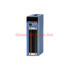
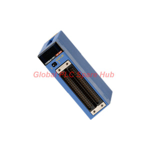
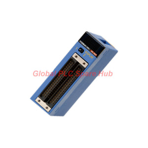
F3YD08-7A Yokogawa 12–24 V DC Sink-Type Transistor Output Module
Manufacturer: Yokogawa
Product No.: F3YD08-7A
Condition: In stock
Product Type: Transistor Output Module
Product Origin: USA
Payment: T/T, Western Union
Weight: 500g
Shipping port: Xiamen
Warranty: 12 months
Estimate delivery times: 12-26 days (International), 3-6 days (United States).
Return within 30 days of purchase. Duties & taxes are non-refundable.
Guaranteed Safe Checkout
Yokogawa F3YD08-7A | 8-Point Transistor Output Module
The F3YD08-7A is an 8-point transistor output module designed for Yokogawa FA-M3 programmable controllers. It provides sink-type DC switching for industrial control loads operating at 12–24 V DC.
Each output point supports a maximum load current of 2 A, with a maximum of 8 A per common. Photocoupler isolation separates the output circuits from the internal control circuitry. A fast response time of 1 ms maximum in both switching directions supports applications that require prompt and repeatable output operation.
01 | Output Architecture at a Glance
| Parameter | Specification |
|---|---|
| Output technology | Transistor contact, sink type |
| Output channels | 8 points |
| Points per common | 8 points/common |
| Rated load voltage | 12–24 V DC |
| Maximum current per point | 2 A |
| Maximum current per common | 8 A |
| Isolation | Photocoupler isolation |
| Surge protection | Active clamp |
02 | Switching Performance
The module is intended for DC output circuits where predictable switching behavior is important. Its key electrical characteristics are listed below.
| Characteristic | Value |
|---|---|
| OFF to ON response time | 1 ms maximum |
| ON to OFF response time | 1 ms maximum |
| ON voltage | 0.5 V DC maximum |
| OFF-state leakage current | 0.1 mA maximum |
| Service life | Not specified in the supplied data |
03 | CPU Error Output Behavior
The output state during a CPU error depends on the CPU type. This setting should be checked during system design and commissioning.
| CPU Type | HOLD / RESET Behavior |
|---|---|
| Sequence CPU | Initial setting: RESET |
| BASIC CPU | No setting function; always HOLD |
| OS-free CPU | Initial setting: HOLD; configurable for each group of 8 points |
All module outputs can also be set collectively. Confirm the applicable CPU documentation and project safety requirements before selecting the error-state behavior. HOLD and RESET determine output behavior during a CPU error; they should not be treated as a substitute for an independent safety circuit.
04 | Power and Connection Requirements
| Item | Specification |
|---|---|
| Internal current consumption | 80 mA at 5 V DC |
| External supply | 12–24 V DC |
| External supply current | 10 mA |
| External connection | 10-point terminal block |
| Terminal screw | M3.5 |
| Weight | Approx. 130 g |
05 | Environmental Operating Limits
| Condition | Operating | Storage |
|---|---|---|
| Ambient temperature | 0 to 55°C | -20 to 75°C |
| Relative humidity | 10 to 90% RH, non-condensing | 10 to 90% RH, non-condensing |
The installation environment must be free from corrosive gases, flammable gases, and heavy dust. Maintain adequate ventilation and avoid condensation inside the control cabinet.
06 | Engineering Notes for Selection and Commissioning
- Check the load current: The maximum rating is 2 A per output point and 8 A per common. Verify both limits when several loads operate simultaneously.
- Confirm sink-type wiring: Check the load polarity and DC supply arrangement against the module terminal diagram before energizing the circuit.
- Review inductive loads: Solenoids, relays, and contactor coils can generate transient voltage. The module uses an active clamp, but the load and wiring design must still follow the manufacturer's requirements.
- Check OFF-state leakage: The specified leakage is up to 0.1 mA. For low-current loads, confirm that this value will not cause unintended activation or residual voltage problems.
- Verify CPU error settings: Confirm whether the application requires HOLD or RESET behavior and check the setting supported by the installed CPU type.
- Inspect terminal connections: Use the correct M3.5 terminal hardware and tighten connections to the manufacturer's specified torque.
07 | Typical Control Applications
- DC solenoid valve and actuator control
- Relay and contactor coil switching within the rated limits
- Industrial machine sequence control
- Packaging and material-handling equipment
- PLC-controlled auxiliary devices and process equipment
- Replacement or maintenance of compatible FA-M3 output configurations
Before using the module with a specific field device, check the device's operating current, inrush characteristics, polarity, and switching requirements against the module ratings.
08 | Model Identification
| Model Code | Configuration |
|---|---|
| F3YD08 | Transistor output module, 8 points |
| -7A | Sink-type output, 12–24 V DC, 2 A per point |
Complete model: F3YD08-7A
09 | Supply and Technical Support
- Product: Yokogawa F3YD08-7A TR Output Module
- Condition: New & Original in Factory Packing
- Warranty: Factory Warranty: 12 Months
- Shipping: FedEx, UPS, DHL
- Support: Model verification and technical selection assistance
Contact our team with your required quantity and delivery destination for a quotation. For replacement projects, provide the existing module model and CPU type so that the configuration can be checked before ordering.
10 | Global PLC Spare HUB Engineering Insight
When selecting a transistor output module, the per-point current rating alone is not enough. The total current through the common group is equally important. For the F3YD08-7A, eight outputs share one common, with a maximum common current of 8 A. A design that uses several high-current loads at the same time must therefore be checked against both the 2 A point limit and the 8 A common limit.
Another important commissioning detail is the OFF-state leakage current. Loads with very low input current may respond differently from conventional relay coils. Checking the field device's minimum operating current and the module's leakage specification can help prevent unexpected output behavior during machine startup or shutdown.
11 | Frequently Asked Questions
Q1: What should be checked if an output indicator is ON but the connected device does not operate?
Start by measuring the voltage at the field device and checking the DC supply polarity. Then inspect the common wiring, terminal tightness, load continuity, and actual current demand. An active PLC output does not by itself confirm that the field circuit is complete.
Q2: Can all eight outputs be used at their maximum rated current simultaneously?
No. The rating is 2 A per point, but the shared common is limited to 8 A. Eight outputs each drawing 2 A would demand 16 A in total. The actual load combination must remain within the common-current limit.
Q3: Why might a low-current electronic load remain slightly active when the output is OFF?
The output has a specified OFF-state leakage current of up to 0.1 mA. Some high-impedance electronic inputs can react to a small residual current. Check the input circuit requirements and consider an appropriate interface solution approved for the application.
Q4: What information is useful when replacing an existing output module?
Record the complete module number, CPU model, terminal wiring, field supply voltage, and connected load current. Also document the required CPU-error output behavior. These details help identify configuration differences that may not be obvious from the module's physical appearance.
Q5: What is a practical way to diagnose intermittent output operation?
Monitor the DC supply while the load is switching, inspect shared common connections, and check whether the total current approaches the 8 A limit. Also review cable routing and terminal condition. If the problem occurs only when several loads operate together, investigate common-group loading before replacing the module.
Tags
Q: Are these parts 100% original and new?
A: Yes. Every component is guaranteed to be 100% original, brand-new, and factory-sealed. We also provide a 12-month comprehensive warranty for your peace of mind.
Q: How fast is the shipping to my country?
A: For in-stock items, we offer same-day dispatch. International express shipping (DHL/FedEx/UPS) typically delivers within 3–5 business days worldwide.
Q: Can I get a formal quotation with shipping costs?
A: Absolutely. Our sales team is ready to provide a detailed Proforma Invoice (PI) including the most competitive shipping rates for your location.
Q: Do you offer discounts for bulk orders?
A: We provide volume-based pricing for large projects or multiple-item orders. Please contact us to get our Best Price Guarantee.
12-Month Comprehensive Warranty
Every part supplied by Global PLC Spare Hub is covered by a 12-month warranty from the date of invoice.
- Coverage: Functional defects and hardware failures under normal operating conditions.
- Commitment: We provide immediate repair, replacement, or a full refund for any verified defective components to minimize your operational downtime.
Returns & Exchange Policy
We offer a 30-day return policy to ensure you receive the exact part your system requires.
- Eligibility: Returns are accepted for uninstalled items in their original, factory-sealed packaging.
- RMA Process: Please contact our support team to obtain a Return Merchandise Authorization (RMA) number before shipping.
- Fast Processing: Refunds or exchanges are processed within 3–5 business days after the returned item passes our technical inspection.
Need Technical Assistance?Not sure if this part is compatible with your system? [Consult our Engineers] before purchasing to ensure 100% compatibility.
People Also Bought


