


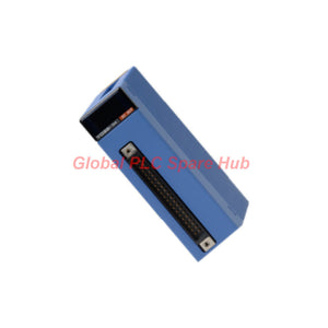
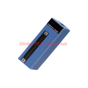
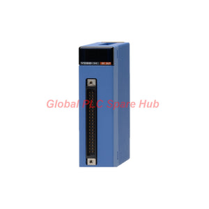
F3YD32-1P High-Reliability Sink Output Module by Yokogawa FA-M3
Manufacturer: Yokogawa
Product No.: F3YD32-1P
Condition: In stock
Product Type: Sink Output Module
Product Origin: JP
Payment: T/T, Western Union
Weight: 500g
Shipping port: Xiamen
Warranty: 12 months
Estimate delivery times: 12-26 days (International), 3-6 days (United States).
Return within 30 days of purchase. Duties & taxes are non-refundable.
Guaranteed Safe Checkout
F3YD32-1P | Yokogawa FA-M3 32-Point Transistor Output Module
The YOKOGAWA F3YD32-1P is a 32-point transistor output module for the FA-M3 programmable controller platform. It provides 12–24 VDC sink-type outputs for controlling compatible field loads.
The module uses photocoupler isolation between the external connection terminals and internal circuitry. Its output architecture supports eight points per common, with a maximum load current of 0.1 A per point and 0.5 A per common.
Built-in short-circuit and overheat protection help protect the output elements during abnormal load conditions. An active clamp circuit provides output surge protection. These functions make the module suitable for distributed DC control signals in machine automation and process equipment.
01 | Output Architecture — 32 Channels, Four Common Groups
The F3YD32-1P uses NPN-style sink output behavior. Each output switches its load return path, so the external load circuit must be wired for sink-type operation.
- Output technology: Transistor, sink type.
- Output channels: 32 points.
- Common arrangement: 8 points per common.
- Isolation: Photocoupler isolation.
- External load voltage: 12–24 VDC.
- Operating voltage range: 10.2–26.4 VDC.
The 8-point common arrangement is important when distributing field power. Plan the external supply and load returns by common group rather than treating all 32 points as one unrestricted output bank.
02 | Load Capacity and Switching Characteristics
Output loading must remain within both the individual channel rating and the common-group rating. A channel may meet its individual current limit while the combined load exceeds the common limit.
| Electrical Parameter | Rated Value |
| Maximum current per point | 0.1 A |
| Maximum current per common | 0.5 A |
| OFF-to-ON response | 1 ms maximum |
| ON-to-OFF response | 1 ms maximum |
| ON voltage | 0.5 VDC maximum |
| OFF-state leakage current | 0.1 mA maximum |
For example, eight loads rated at 100 mA each would total 800 mA. This exceeds the 0.5 A common rating, even though each load is within the 0.1 A individual limit.
Check the actual operating current of solenoids, indicator lamps, and interface relays. Consider inrush current and the load manufacturer's electrical data before assigning output points.
03 | Protection Design — Short Circuit, Overheat and Surge
The module incorporates several protective functions. They address different electrical fault conditions and should not be treated as interchangeable.
- Short-circuit protection: Limits output current or temporarily turns the output off when an abnormal condition is detected.
- Overheat protection: Turns off the affected output group when the output element temperature exceeds its protection threshold.
- Surge protection: Uses an active clamp circuit.
- Fuse: No built-in fuse.
Short-circuit protection operates individually on output points. Overheat protection operates in groups of eight points: OUT1–OUT8, OUT9–OUT16, OUT17–OUT24, and OUT25–OUT32.
If a short circuit remains, the output element may continue to heat up. The module should not be left in a prolonged short-circuit condition. Remove the fault and verify normal operation before returning the channel to service.
Inductive load warning: When driving a relay coil or another inductive load, install a suitable surge suppressor or diode across the load. The module's active clamp does not eliminate the need for appropriate load-side suppression.
04 | CPU Stop Behavior — HOLD or RESET
The output state when the control program stops depends on the CPU type and its configuration. This behavior should be reviewed during machine safety and restart design.
- Sequence CPU: Initial setting is RESET. The output behavior can be configured globally on a module-by-module basis.
- BASIC CPU: No setting function is provided. The output state is always HOLD.
- OS-free CPU: Initial setting is HOLD. The state can be specified for each group of eight points.
Do not assume that every CPU automatically resets the outputs when the program stops. Verify the installed CPU type, module settings, and machine restart sequence.
For equipment controlling actuators or process valves, evaluate the consequences of both HOLD and RESET behavior. Use independent safety circuits where the application requires a defined safe state.
05 | External Wiring and Power Requirements
The F3YD32-1P connects to external field wiring through one 40-pin connector. Correct connector wiring and supply polarity are essential to reliable operation.
- External connection: One 40-pin connector.
- External power supply: 12–24 VDC.
- External supply current: 55 mA.
- Internal module consumption: 160 mA at 5 VDC.
- Output indication: LED, illuminated when the output is ON.
- Withstand voltage: 1,500 VAC for one minute between the external connection terminal group and internal circuit.
Check the connector pin assignment before connecting a replacement cable. Yokogawa warns that a connector wired for F3XD32 or F3XD64 input modules must not be incorrectly connected to this output module. Incorrect wiring can disable protective functions and damage internal components.
06 | Installation Environment
Install the module in a control cabinet that meets the specified environmental conditions.
- Operating temperature: 0–55°C.
- Storage temperature: -20–75°C.
- Operating humidity: 10–90% RH, non-condensing.
- Storage humidity: 10–90% RH, non-condensing.
- Atmosphere: Free from corrosive gases, flammable gases, and heavy dust.
- Weight: Approximately 110 g.
Maintain adequate cabinet ventilation. Avoid installation locations exposed to condensation, corrosive atmospheres, or excessive dust.
07 | Typical Control Applications
The 32-point sink output architecture is suitable for switching compatible DC field devices in automated equipment.
- Solenoid valve control: Switching compatible 12–24 VDC valve coils within the current rating.
- Relay interface control: Driving external interface relays with suitable coil suppression.
- Machine status outputs: Controlling DC indicator devices and status signals.
- Interlock circuits: Providing PLC output commands to external control interfaces.
- Distributed control panels: Organizing field outputs into four common groups.
Confirm load current, inductive characteristics, and external circuit protection before connecting field devices.
08 | Technical Specifications
| Item | Specification |
| Model | F3YD32-1P |
| Brand | Yokogawa |
| Series | FA-M3 |
| Module type | Transistor output module |
| Output type | Sink type |
| Number of points | 32 |
| Common arrangement | 8 points/common |
| Isolation method | Photocoupler isolation |
| Withstand voltage | 1,500 VAC, 1 minute |
| Rated load voltage | 12–24 VDC |
| Operating voltage range | 10.2–26.4 VDC |
| Maximum load current | 0.1 A/point; 0.5 A/common |
| OFF-to-ON response | 1 ms maximum |
| ON-to-OFF response | 1 ms maximum |
| ON voltage | 0.5 VDC maximum |
| OFF-state leakage current | 0.1 mA maximum |
| Short-circuit protection | Current limiting or output shutdown |
| Overheat protection | Output shutdown, 8-point group control |
| Surge protection | Active clamp circuit |
| Fuse | None |
| Internal current consumption | 160 mA at 5 VDC |
| External power supply | 12–24 VDC, 55 mA |
| Output indication | LED, ON when output is active |
| External connector | One 40-pin connector |
| Weight | 110 g |
| Operating temperature | 0–55°C |
| Storage temperature | -20–75°C |
| Operating humidity | 10–90% RH, non-condensing |
| Storage humidity | 10–90% RH, non-condensing |
| Operating atmosphere | Free from corrosive gases, flammable gases, and heavy dust |
09 | Frequently Asked Questions
Q1: Why does a field device fail to operate even when the output LED is illuminated?
The LED indicates the module's output command state, but it does not confirm that the complete field circuit is operating correctly. Check the external 12–24 VDC supply, load wiring, common connection, and device coil resistance. Measure the voltage across the load while the output is commanded ON. Also inspect connector wiring and external circuit continuity.
Q2: Can the module directly drive a 24 VDC solenoid valve?
It can drive a compatible valve coil if the steady-state current remains within 0.1 A per point and 0.5 A per common. Check the coil's inrush characteristics and switching requirements. Install a suitable suppression diode or surge suppressor across the coil. If the load exceeds the rating, use an appropriately rated interposing relay or driver.
Q3: Why might several outputs in the same group turn off together?
Check whether the affected points share the same eight-point common group. A common wiring fault, excessive group loading, or overheat protection event can affect multiple outputs. Measure the total group current and inspect the wiring for short circuits. Compare the affected points with outputs in other groups to narrow down the fault location.
Q4: What should be checked before replacing this module in an existing FA-M3 rack?
Confirm the exact model suffix, output direction, connector wiring, external supply polarity, and CPU stop-state configuration. Do not substitute a source-type or TTL output module based only on its 32-point count. Also check the field cable against the correct output-module pin assignment before energizing the replacement.
Q5: How should intermittent output shutdown be investigated?
Start by checking the load current under actual operating conditions. Inspect for intermittent cable shorts, loose terminals, damaged coil insulation, and excessive common-group loading. If shutdown occurs after several outputs operate together, check the eight-point group current and cabinet temperature. Remove the fault before testing again; repeated short-circuit operation can cause thermal damage.
10 | Replacement and Ordering Checks
Before selecting the F3YD32-1P for a replacement or expansion project, verify the following:
- Exact model number: F3YD32-1P.
- FA-M3 system and installed CPU compatibility.
- 32-point transistor sink output requirement.
- 12–24 VDC field supply and load polarity.
- Maximum current per point and per common.
- 40-pin connector and field cable pin assignment.
- Required HOLD or RESET behavior when the program stops.
The F3YD32-1P is not a direct substitute for the F3YD32-1R source output version or the F3YD32-1T TTL output version. Confirm the output circuit before ordering.
Tags
Q: Are these parts 100% original and new?
A: Yes. Every component is guaranteed to be 100% original, brand-new, and factory-sealed. We also provide a 12-month comprehensive warranty for your peace of mind.
Q: How fast is the shipping to my country?
A: For in-stock items, we offer same-day dispatch. International express shipping (DHL/FedEx/UPS) typically delivers within 3–5 business days worldwide.
Q: Can I get a formal quotation with shipping costs?
A: Absolutely. Our sales team is ready to provide a detailed Proforma Invoice (PI) including the most competitive shipping rates for your location.
Q: Do you offer discounts for bulk orders?
A: We provide volume-based pricing for large projects or multiple-item orders. Please contact us to get our Best Price Guarantee.
12-Month Comprehensive Warranty
Every part supplied by Global PLC Spare Hub is covered by a 12-month warranty from the date of invoice.
- Coverage: Functional defects and hardware failures under normal operating conditions.
- Commitment: We provide immediate repair, replacement, or a full refund for any verified defective components to minimize your operational downtime.
Returns & Exchange Policy
We offer a 30-day return policy to ensure you receive the exact part your system requires.
- Eligibility: Returns are accepted for uninstalled items in their original, factory-sealed packaging.
- RMA Process: Please contact our support team to obtain a Return Merchandise Authorization (RMA) number before shipping.
- Fast Processing: Refunds or exchanges are processed within 3–5 business days after the returned item passes our technical inspection.
Need Technical Assistance?Not sure if this part is compatible with your system? [Consult our Engineers] before purchasing to ensure 100% compatibility.
People Also Bought


