


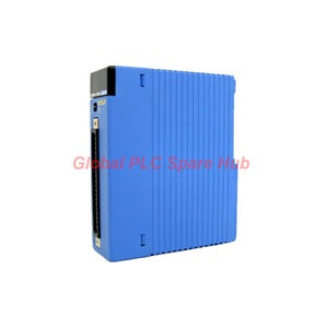
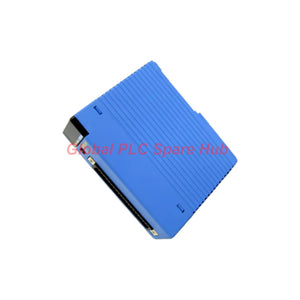
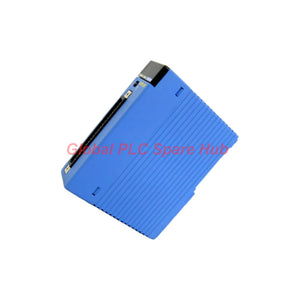
F3XD64-6M Yokogawa FA-M3 64-Point Matrix Scan DC Input Module
Manufacturer: Yokogawa
Product No.: F3XD64-6M
Condition: In stock
Product Type: DC Input Module
Product Origin: JP
Payment: T/T, Western Union
Weight: 500g
Shipping port: Xiamen
Warranty: 12 months
Estimate delivery times: 12-26 days (International), 3-6 days (United States).
Return within 30 days of purchase. Duties & taxes are non-refundable.
Guaranteed Safe Checkout
Yokogawa F3XD64-6M – 64-Point Matrix Scan DC Input Module
The Yokogawa F3XD64-6M is a 64-point DC input module designed for the FA-M3 programmable controller platform. It uses a matrix scan input architecture to acquire discrete signals from external devices, with photocoupler isolation between the field input circuits and the internal logic.
Supporting a rated input voltage of 12–24 VDC, the module accepts digital status signals from compatible field devices such as limit switches, auxiliary contacts, and other discrete control components. Its 64 input points are organized as an 8 × 8 matrix, providing a compact I/O arrangement for applications that require multiple status signals within a limited module footprint.
Unlike conventional point-to-point input arrangements, matrix scan wiring requires attention to the common-line structure and external connection assignment. Correct wiring and controller configuration are therefore important to ensure that each field signal is interpreted at the intended input address.
Module Identity and Configuration
| Identification | Specification |
|---|---|
| Manufacturer | Yokogawa |
| Model | F3XD64-6M |
| Product family | FA-M3 |
| Product type | DC input matrix scan module |
| Input architecture | Matrix scan |
| Input capacity | 64 points |
| Isolation | Photocoupler isolation |
| Rated input voltage | 12–24 VDC |
| External connection | One 40-pin connector |
| Common arrangement | 8 × 8 matrix |
| Interrupt function | None |
Understanding the -6M Configuration
The supplied model identification describes the F3XD64-6M as a 12–24 VDC, 64-point matrix scan input module.
- F3XD64: FA-M3 digital input module designation with 64 input points.
- -6M: Matrix scan DC input configuration, rated for 12–24 VDC.
- Functional arrangement: 64 inputs organized into an 8 × 8 matrix.
For replacement projects, confirm the complete model suffix rather than selecting a module based only on its 64-point capacity. Matrix scan and conventional digital input modules may have different wiring arrangements and cannot be assumed to be interchangeable.
Electrical Input Characteristics
| Electrical Parameter | Value |
|---|---|
| Rated input voltage | 12–24 VDC |
| Rated input current at 12 VDC | 3.9 mA |
| Rated input current at 24 VDC | 8.2 mA |
| Operating voltage range | 10.2–26.4 VDC |
| ON-state voltage | 8.0 VDC minimum |
| ON-state current | 2.6 mA minimum |
| OFF-state voltage | 3.4 VDC maximum |
| OFF-state current | 1.0 mA maximum |
| OFF-to-ON response time | 16 ms maximum |
| ON-to-OFF response time | 16 ms maximum |
| Maximum simultaneous ON ratio | Not specified |
The ON/OFF thresholds define the electrical conditions under which the module recognizes a field input as active or inactive. When selecting field switches or interfacing devices, check their output voltage and leakage current against these thresholds.
For example, a field device with significant OFF-state leakage may keep the input voltage above the expected OFF threshold. This can result in an input that remains active or changes state intermittently. Verify the actual voltage at the module terminals when diagnosing unexpected status indications.
Matrix Scan Architecture and Wiring
The 8 × 8 matrix arrangement organizes 64 input points through a shared matrix connection structure. The module uses one 40-pin external connector, so the wiring interface and signal assignment must match the applicable Yokogawa connection diagram.
During panel design and commissioning, pay particular attention to:
- Matrix line identification: Label row and column connections clearly to prevent input-address mapping errors.
- Connector compatibility: Confirm the mating connector, cable assembly, and pin assignment before wiring.
- Signal grouping: Keep field-device wiring consistent with the assigned matrix positions.
- Electrical reference: Follow the specified common-line and external supply arrangement.
- Controller mapping: Verify that the PLC program associates each physical matrix position with the intended process tag.
A matrix scan module should not be wired using a generic 64-point digital input pinout. Always use the connection information for the exact F3XD64-6M configuration.
Response Time and Control-System Application
The module specifies a maximum response time of 16 ms for both OFF-to-ON and ON-to-OFF transitions. This response characteristic is relevant when evaluating whether the input module can capture the switching behavior of the connected field device.
It is suitable for general discrete status acquisition, including:
- Machine operating and stopped feedback
- Limit-switch and position status monitoring
- Auxiliary contact state acquisition
- Equipment interlock status signals
- Discrete process and panel status collection
The module has no interrupt function. Applications that depend on interrupt-driven event capture or very short-duration pulse detection should be evaluated carefully. The specified response time alone does not establish suitability for every high-speed event application.
Power Consumption and Physical Data
| Parameter | Specification |
|---|---|
| Internal current consumption | 110 mA at 5 VDC |
| Weight | 130 g |
| External connector | One 40-pin connector |
| Input isolation | Photocoupler |
The stated 110 mA at 5 VDC is the module's internal current consumption. It should be included in the controller's backplane or system power budget, separately from the field-side 12–24 VDC input circuits.
Operating Environment
| Environmental Parameter | Operating Condition | Storage Condition |
|---|---|---|
| Ambient temperature | 0 to 55°C | -20 to 75°C |
| Relative humidity | 10–90% RH, non-condensing | 10–90% RH, non-condensing |
| Atmosphere | Free of corrosive gases, flammable gases, and heavy dust | Protect from unsuitable storage conditions |
Install the module in a suitable control cabinet with adequate ventilation and protection from conductive dust, corrosive gases, and condensation. Maintaining the specified environmental conditions helps reduce connector degradation and intermittent I/O faults.
Commissioning and Fault Isolation
- Check module identification: Confirm F3XD64-6M against the system hardware list and installed module label.
- Inspect the 40-pin connection: Check connector seating, pin condition, cable integrity, and terminal labeling.
- Measure field voltage: Verify that the input signal remains within the 10.2–26.4 VDC operating range.
- Test ON/OFF thresholds: Compare measured input voltage and current with the specified recognition levels.
- Validate matrix mapping: Operate field devices individually and confirm that the correct PLC input addresses change state.
- Review response behavior: Check whether the field device's switching duration is compatible with the module's 16 ms maximum response time.
If several input points show incorrect states simultaneously, inspect the shared matrix wiring and connector before troubleshooting each field device separately. A common-line wiring fault can affect multiple logical input points and create misleading symptoms.
Replacement Selection: What Engineers Should Verify
For a maintenance replacement, compare the complete model number, input voltage class, matrix scan arrangement, 40-pin connector, and 8 × 8 common structure. A module with the same number of input points may still use a different electrical interface or input organization.
Also check the control program's input mapping and the field wiring documentation. If the replacement is installed in an existing cabinet, verify that the connector and cable assembly are suitable for the exact module variant before applying field power.
Warranty and Shipping
- Warranty: 12 months.
- Shipping methods: FedEx, UPS, and DHL.
- Ordering support: Provide the full model number and system application details for compatibility verification.
Frequently Asked Questions
1. Why might several input addresses change together when only one field switch operates?
This symptom can indicate an incorrect matrix connection, crossed row or column wiring, or an input mapping error. Check the 40-pin connector assignment against the module wiring diagram. Then operate individual field devices and compare their physical positions with the PLC input addresses. Avoid changing the program mapping until the wiring has been verified.
2. Can this module be used to capture a short pulse from a proximity switch?
Suitability depends on the pulse duration and the complete input acquisition behavior. The stated maximum transition response is 16 ms, and the module has no interrupt function. Very short pulses may not be reliably represented in the controller data. For pulse counting or high-speed event capture, select an input solution specifically rated for that application.
3. What should be investigated when an input remains ON after the field contact opens?
Measure the voltage at the module input with the contact open. The specified OFF-state voltage is 3.4 VDC maximum, with an OFF-state current of 1.0 mA maximum. Leakage through electronic sensors, indicator circuits, or long cable runs can prevent the signal from falling below the OFF threshold. Check the field device output characteristics and wiring before replacing the module.
4. How should engineers test a suspected photocoupler input fault?
First verify the field-side voltage and current at the relevant input. Then use an approved test source and the manufacturer's connection procedure to check whether the input state changes correctly. If the electrical signal is within specification but the corresponding controller status does not change, inspect the connector, matrix wiring, and module condition. Do not apply an external test voltage outside the stated operating range.
5. What details are most important when selecting a spare for an existing FA-M3 installation?
Record the exact F3XD64-6M suffix, the 12–24 VDC input requirement, the 64-point matrix arrangement, the 40-pin connector type, and the existing field wiring assignment. Also check the controller's hardware configuration and available 5 VDC power budget. These checks help prevent a physically similar but electrically incompatible module from being installed.

Tags
Q: Are these parts 100% original and new?
A: Yes. Every component is guaranteed to be 100% original, brand-new, and factory-sealed. We also provide a 12-month comprehensive warranty for your peace of mind.
Q: How fast is the shipping to my country?
A: For in-stock items, we offer same-day dispatch. International express shipping (DHL/FedEx/UPS) typically delivers within 3–5 business days worldwide.
Q: Can I get a formal quotation with shipping costs?
A: Absolutely. Our sales team is ready to provide a detailed Proforma Invoice (PI) including the most competitive shipping rates for your location.
Q: Do you offer discounts for bulk orders?
A: We provide volume-based pricing for large projects or multiple-item orders. Please contact us to get our Best Price Guarantee.
12-Month Comprehensive Warranty
Every part supplied by Global PLC Spare Hub is covered by a 12-month warranty from the date of invoice.
- Coverage: Functional defects and hardware failures under normal operating conditions.
- Commitment: We provide immediate repair, replacement, or a full refund for any verified defective components to minimize your operational downtime.
Returns & Exchange Policy
We offer a 30-day return policy to ensure you receive the exact part your system requires.
- Eligibility: Returns are accepted for uninstalled items in their original, factory-sealed packaging.
- RMA Process: Please contact our support team to obtain a Return Merchandise Authorization (RMA) number before shipping.
- Fast Processing: Refunds or exchanges are processed within 3–5 business days after the returned item passes our technical inspection.
Need Technical Assistance?Not sure if this part is compatible with your system? [Consult our Engineers] before purchasing to ensure 100% compatibility.
People Also Bought


