


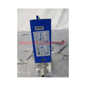
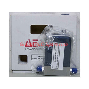
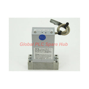
FC-D982 AERA High-Flow Piezoelectric MFC Metal-Sealed Digital Controller
Manufacturer: AERA
Product No.: FC-D982
Condition: In stock
Product Type: Digital Controller
Product Origin: USA
Payment: T/T, Western Union
Weight: 500g
Shipping port: Xiamen
Warranty: 12 months
Estimate delivery times: 12-26 days (International), 3-6 days (United States).
Return within 30 days of purchase. Duties & taxes are non-refundable.
Guaranteed Safe Checkout
FC-D982 | AERA | FC-D980 Series High-Flow Digital Mass Flow Controller
The AERA FC-D982 is a high-flow digital mass flow controller designed for semiconductor gas delivery and process equipment. It belongs to the FC-D980 Series, which combines digital control, piezoelectric actuation, and all-metal sealing.
With a full-scale capacity of 30–50 slm, the FC-D982 serves applications that require higher gas throughput. Its double VAR type 316L stainless steel construction supports demanding ultra-clean gas systems. Engineers can select standard 1/4-inch or 3/8-inch VCR connections according to the installation configuration.
The controller also supports field-programmable multi-gas operation. It stores up to eight gases, with up to 11 calibration points per gas. This configuration gives process engineers greater flexibility when managing different gas recipes.
01 | Model Positioning: High-Flow FC-D980 Configuration
| Manufacturer | AERA |
| Model | FC-D982 |
| Product Family | FC-D980 Series |
| Product Type | Digital Mass Flow Controller (MFC) |
| Control Technology | Digital control with piezoelectric valve |
| Flow Capacity | 30–50 slm |
| Gas Configuration | Field-programmable multi-gas |
| Sealing Design | All-metal seals |
| Connection Options | 1/4-inch or 3/8-inch VCR |
02 | Measurement Performance: Accuracy Across the Operating Range
The FC-D982 specifies accuracy in two separate flow regions. Engineers should use the appropriate reference basis when calculating process uncertainty.
| Full-Scale Flow Range | 30–50 slm |
| Accuracy at 25–100% FS | Within ±1% of setpoint |
| Accuracy at 2–25% FS | Within ±0.25% of full scale |
| Repeatability | Within ±0.2% of full scale |
| Response Time | Less than 1 second to within ±2% of setpoint |
| Control Range | 2–100% FS |
| Zero Stability | Less than 0.5% FS over one year |
Performance interpretation: The accuracy specification changes its reference basis at 25% FS. The upper operating region uses setpoint-based accuracy. The lower region uses full-scale-based accuracy.
For example, a 50 slm configuration has a lower-region accuracy specification referenced to 50 slm full scale. Engineers should not interpret ±0.25% FS as ±0.25% of the commanded flow.
03 | Gas Management: Flexible Multi-Gas Configuration
The digital architecture supports multiple gas configurations within one controller.
- Gas storage: Stores up to eight gas configurations.
- Calibration data: Supports up to 11 calibration points per gas.
- Gas selection: Allows field-programmable gas configuration.
- Process flexibility: Supports equipment that uses multiple gas recipes.
Gas selection and calibration data must match the actual process gas. Do not assume that one gas calibration automatically provides accurate measurement for another gas.
04 | Wetted Construction: Ultra-Clean Gas Path
| Wetted Material | Double VAR type 316L stainless steel |
| Surface Treatment | Electropolished and ultra-cleaned |
| Surface Finish | 1 Ra (0.025 µm), as specified |
| Sealing Method | All-metal seals |
| Fitting Options | 1/4-inch or 3/8-inch VCR |
| Helium Leak Rate | 1 × 10⁻¹⁰ atm·cc/sec maximum |
The double VAR 316L construction and electropolished surface support clean gas delivery. Metal sealing avoids reliance on elastomer seals in the specified gas-wetted sealing configuration.
Before installation, verify the gas compatibility of all wetted components. Stainless steel and metal seals do not guarantee compatibility with every corrosive gas or process condition.
05 | Pressure and Environmental Operating Window
| Operating Differential Pressure | 28–40 psiD (194–275 kPaD) |
| Maximum Operating Pressure | 70 psig (490 kPaG) |
| Proof Pressure | 140 psig (981 kPaG) |
| Operating Temperature | 5–45°C (41–113°F) |
| Heated Configuration | No; standard unheated version |
Maintain the specified differential pressure during operation. The maximum operating pressure and proof pressure describe different limits. Proof pressure does not represent an allowable continuous operating condition.
06 | Electrical Control and Valve Architecture
| Analog Setpoint | 0–5 VDC |
| Analog Output | 0–5 VDC |
| Digital Interface | RS-485 |
| Connector | 20-pin Honda connector |
| Positive Supply | +15 VDC ±2%, 120 mA minimum |
| Negative Supply | −15 VDC ±2%, 50 mA minimum |
| Maximum Power | 1.3 W |
| Valve Technology | Piezoelectric actuator |
| Valve Configuration | Normally open or normally closed |
The specified valve configuration can be normally open or normally closed. Confirm the actual valve option before connecting the controller to a process gas supply.
07 | Mechanical Envelope and Installation Interface
| Height | 142 mm |
| Width | 38 mm |
| Depth | 183.8 mm |
| Port-to-Port Dimension | 183.8 mm |
| Weight | 1.8 kg (3.9 lb) |
Check the outline drawing before modifying the gas panel. Confirm port orientation, service clearance, fitting size, and mounting position. The 3/8-inch VCR option may affect the required installation space.
08 | Semiconductor Process Applications
- CVD: Controls process gas delivery in chemical vapor deposition equipment.
- PVD: Supports gas-flow control in physical vapor deposition systems.
- Etching: Provides controlled gas delivery for plasma etch processes.
- Diffusion: Supports gas supply in semiconductor thermal processing equipment.
- Ion implantation: Provides flow control for compatible gas delivery systems.
- Sputtering: Supports gas regulation in sputtering process equipment.
09 | Commissioning and Maintenance: Practical Checks
- Verify the full-scale range. Confirm that the installed unit matches the process flow requirement.
- Check the gas selection. Confirm the programmed gas and calibration data before applying a setpoint.
- Confirm the valve option. Identify normally open or normally closed operation from the unit configuration.
- Inspect the VCR connections. Match the fitting size and sealing hardware to the gas panel.
- Check pressure conditions. Maintain the required differential pressure during flow verification.
- Validate electrical signals. Confirm supply polarity, analog scaling, and RS-485 communication.
- Verify zero stability. Check zero output under the manufacturer's specified conditions before evaluating low-flow performance.
For process troubleshooting, separate gas-supply problems from controller-related problems. Check inlet pressure, outlet pressure, gas selection, and signal scaling before adjusting the flow-control system.
10 | Compliance and Product Identification
- RoHS: Compliant as specified.
- SEMI reference: SEMI E17-91.
- Series architecture: Digital, piezoelectric, metal-sealed FC-D980 family.
- Configuration: Standard unheated version.
Confirm the applicable compliance documentation and product revision before using the unit in a regulated equipment qualification process.
11 | Frequently Asked Questions
Q1: What is the practical difference between a 30 slm and a 50 slm configuration?
The selected full-scale range determines the measurement and control span. A 30 slm unit may suit a process with lower maximum demand. A 50 slm unit provides greater capacity when the recipe requires higher flow. Compare actual operating points rather than selecting solely by maximum process demand.
Q2: Can the stored gas configurations be changed during equipment operation?
The controller supports field-programmable gas configurations. However, the safe procedure for changing gases depends on the equipment control system and process recipe. Confirm the gas-selection command, transition sequence, and interlocks before implementing changes during production.
Q3: How should engineers evaluate low-flow performance during acceptance testing?
Use a calibrated reference instrument with suitable uncertainty at the intended test point. Stabilize gas pressure and temperature first. Then compare readings against the full-scale-based accuracy limit applicable below 25% FS. Avoid using the upper-range accuracy formula for low-flow acceptance.
Q4: What could cause unstable readings after replacing the gas panel fittings?
Check fitting alignment, VCR sealing surfaces, gas leakage, and mechanical stress on the controller ports. Also verify that the replacement fittings match the original connection dimensions. A leak or installation strain can affect process stability even when the electrical interface remains correct.
Q5: How should maintenance teams assess long-term zero drift?
Record zero readings under consistent gas isolation, pressure, and environmental conditions. Compare results over time against the specified annual zero stability. If the reading changes unexpectedly, inspect leakage, residual gas, contamination, and the test setup before concluding that the controller requires recalibration.
Tags
Q: Are these parts 100% original and new?
A: Yes. Every component is guaranteed to be 100% original, brand-new, and factory-sealed. We also provide a 12-month comprehensive warranty for your peace of mind.
Q: How fast is the shipping to my country?
A: For in-stock items, we offer same-day dispatch. International express shipping (DHL/FedEx/UPS) typically delivers within 3–5 business days worldwide.
Q: Can I get a formal quotation with shipping costs?
A: Absolutely. Our sales team is ready to provide a detailed Proforma Invoice (PI) including the most competitive shipping rates for your location.
Q: Do you offer discounts for bulk orders?
A: We provide volume-based pricing for large projects or multiple-item orders. Please contact us to get our Best Price Guarantee.
12-Month Comprehensive Warranty
Every part supplied by Global PLC Spare Hub is covered by a 12-month warranty from the date of invoice.
- Coverage: Functional defects and hardware failures under normal operating conditions.
- Commitment: We provide immediate repair, replacement, or a full refund for any verified defective components to minimize your operational downtime.
Returns & Exchange Policy
We offer a 30-day return policy to ensure you receive the exact part your system requires.
- Eligibility: Returns are accepted for uninstalled items in their original, factory-sealed packaging.
- RMA Process: Please contact our support team to obtain a Return Merchandise Authorization (RMA) number before shipping.
- Fast Processing: Refunds or exchanges are processed within 3–5 business days after the returned item passes our technical inspection.
Need Technical Assistance?Not sure if this part is compatible with your system? [Consult our Engineers] before purchasing to ensure 100% compatibility.
People Also Bought


