


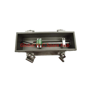
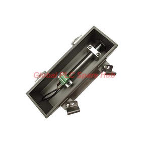
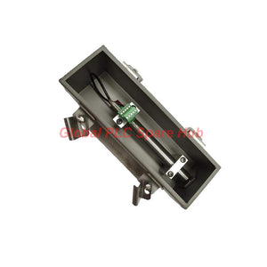
135613-01-01 Bently Nevada High Temperature Series DC Expansion Transducer
Manufacturer: Bently Nevada
Product No.: 135613-01-01
Condition: In stock
Product Type: Case Expansion Transducer Assembly
Product Origin: USA
Payment: T/T, Western Union
Weight: 500g
Shipping port: Xiamen
Warranty: 12 months
Estimate delivery times: 12-26 days (International), 3-6 days (United States).
Return within 30 days of purchase. Duties & taxes are non-refundable.
Guaranteed Safe Checkout
135613-01-01 | Bently Nevada High Temperature Case Expansion Transducer Assembly (DC)
The Bently Nevada 135613-01-01 is a DC-powered case expansion transducer assembly designed to measure relative mechanical displacement in high-temperature machinery monitoring applications. It converts linear movement into a proportional DC voltage signal for compatible monitoring and control systems.
With a 25.4 mm (1.00 in) linear measurement range and a scale factor of 0.20 V/mm (5.0 V/in), this assembly supports case expansion monitoring on large rotating equipment. Its spring-return configuration provides a defined mechanical return arrangement, while the high-temperature design supports operating environments from -25°C to +85°C.
The assembly is suitable for machinery applications where thermal growth and casing movement require continuous measurement. Typical engineering considerations include sensor alignment, mechanical travel, reference position, and signal scaling.
CONFIGURATION BLUEPRINT | Ordering Code Breakdown
| Part Number Segment | Option | Configuration Description |
|---|---|---|
| 135613 | Base Model | High Temperature Case Expansion Transducer Assembly (DC) |
| -01 | Linear Range Option 01 | 25.4 mm (1.00 in) linear range with 127 mm (5.00 in) rod |
| -01 | Spring Option 01 | Spring return |
Complete Ordering Number: 135613-01-01
Configuration hierarchy:
-
135613
- Product family: High Temperature Case Expansion Transducer Assembly
- Signal type: DC output
- Application: Machinery case expansion measurement
-
First suffix -01
- Measurement travel: 25.4 mm (1.00 in)
- Rod length: 127 mm (5.00 in)
-
Second suffix -01
- Mechanical return: Spring return
When ordering a replacement, match both suffixes. The linear travel and spring-return configuration directly affect mechanical installation and measurement setup.
MEASUREMENT SYSTEM | Electrical and Displacement Characteristics
| Parameter | Specification |
|---|---|
| Input Power | +13.5 to +26 VDC, unregulated |
| Minimum Supply Current | 30 mA minimum |
| Output Voltage | +1 to +6 VDC, all models |
| Scale Factor | 0.20 V/mm (5.0 V/in) |
| Linear Measurement Range | 25.4 mm (1.00 in) |
| Output Noise | Less than 10 mV |
| -3 dB Frequency | 200 Hz typical |
| Stability | 0.125% full scale |
| Non-Linearity | Less than 0.25% full scale |
| Temperature Coefficient | Maximum 0.05%/°C (0.028%/°F) |
The transducer provides a nominal output scale of 0.20 V for each millimeter of displacement. Across the specified 25.4 mm travel, the corresponding voltage span is 5 V, consistent with the stated +1 to +6 VDC output range.
The output is suitable for displacement monitoring when the receiving system supports the required DC input range and scaling. Engineers should verify the monitor input configuration and displacement direction before commissioning.
MECHANICAL ASSEMBLY | Dimensions and Mounting
| Mechanical Item | Specification |
|---|---|
| Overall Height | 88.9 mm (3.50 in) |
| Overall Width | 117 mm (4.60 in) |
| Overall Length | 241 mm (9.50 in) |
| Body Length | 171 mm (6.75 in) |
| Body Diameter | 19.2 mm (0.75 in), all models |
| Body End to Null Center | 65.4 mm (2.57 in) |
| Core Length | 87.6 mm (3.45 in) |
| Rod Length | 127 mm (5.00 in) |
| Weight | Approximately 2.3 kg (5.0 lb) |
| Core-End Thread | 6-40 UNF-2B |
| Machine-End Thread | 1/4-20 UNC-2A |
Installation requires adequate mechanical clearance for the complete assembly and its moving components. Confirm the available travel, mounting orientation, rod alignment, and reference position before fixing the transducer to the machine.
THERMAL & ENVIRONMENTAL OPERATING ENVELOPE
| Environmental Parameter | Operating Specification |
|---|---|
| Operating Temperature | -25°C to +85°C (-13°F to +185°F) |
| Storage Temperature | -55°C to +125°C (-67°F to +257°F) |
| Shock Resistance | 250 g for 11 ms |
| Vibration Resistance | 10 g at 0 to 2 kHz |
The operating temperature rating defines the specified working environment. The higher storage temperature limit applies to storage conditions and should not be treated as a continuous operating rating.
APPLICATION ENGINEERING | Where It Is Used
- Steam turbines: Monitoring casing movement caused by thermal expansion during startup, load changes, and shutdown.
- Gas turbines: Measuring structural displacement associated with temperature changes and operating conditions.
- Large rotating machinery: Tracking mechanical case movement to support condition assessment.
- Thermal growth monitoring: Providing displacement feedback for machinery expansion monitoring systems.
- Plant maintenance: Supporting trend analysis and investigation of abnormal casing movement.
Case expansion measurement helps engineers understand how machine structures move as operating temperatures change. Trend data can support the evaluation of thermal growth, mechanical restraint, and potential alignment issues.
INSTALLATION ENGINEERING | Commissioning Procedure
- Verify the mounting arrangement. Confirm the 127 mm rod option, machine-end thread, available mounting space, and mechanical attachment points.
- Check the measurement direction. Establish the reference position and determine the expected direction of case movement.
- Align the moving assembly. Prevent side loading, binding, and unnecessary friction throughout the intended travel.
- Verify the supply voltage. Provide an unregulated +13.5 to +26 VDC supply and confirm adequate current capacity.
- Check the DC output. Confirm that the receiving instrument can accept the +1 to +6 VDC output range.
- Configure signal scaling. Apply the specified 0.20 V/mm scale factor in the monitoring system.
- Perform a movement test. Check output direction, signal stability, and mechanical travel before placing the machine into normal operation.
During troubleshooting, inspect mechanical binding and mounting alignment before replacing the electrical assembly. An incorrect reference position can also create misleading displacement readings even when the transducer operates correctly.
ACCURACY & SIGNAL INTERPRETATION
The scale factor provides a direct relationship between displacement and voltage change. The following examples illustrate the nominal conversion:
| Displacement Change | Nominal Voltage Change |
|---|---|
| 1 mm | 0.20 V |
| 5 mm | 1.00 V |
| 10 mm | 2.00 V |
| 20 mm | 4.00 V |
| 25.4 mm | 5.08 V nominal based on the rounded 0.20 V/mm scale factor |
The specified output range is +1 to +6 VDC over a 25.4 mm linear range. The scale factor is a nominal rounded value. Use the manufacturer's calibration data and actual transfer characteristics for final engineering calculations.
COMPLIANCE & REGULATORY INFORMATION
| Standard / Directive | Compliance Information |
|---|---|
| FCC Part 15 | Complies with the stated Part 15 operating conditions |
| EN 61000-6-2:2005 | Electromagnetic compatibility – industrial immunity |
| EN 61000-6-4:2007 + A1:2011 | Electromagnetic compatibility – industrial emissions |
| EMC Directive | 2014/30/EU |
| RoHS | Directive 2011/65/EU |
| Country of Origin | Made in U.S.A. |
FCC Part 15 operation is subject to two conditions: the device must not cause harmful interference, and it must accept received interference, including interference that may cause undesired operation.
REPLACEMENT SELECTION | Engineering Compatibility Checklist
- Confirm the complete model number: 135613-01-01.
- Match the 25.4 mm linear range and 127 mm rod configuration.
- Verify spring-return mechanical operation.
- Check the +13.5 to +26 VDC power supply requirement.
- Confirm the receiving monitor accepts the +1 to +6 VDC output.
- Verify the 0.20 V/mm scaling and required displacement direction.
- Compare mounting threads, body dimensions, and available mechanical clearance.
- Check the operating temperature and environmental conditions.
For replacement projects, provide the existing transducer part number, installation drawing, and monitor input details. This helps reduce the risk of mechanical mismatch or incorrect signal scaling.
GLOBAL PLC SPARE HUB | MACHINERY APPLICATION INSIGHT
Case expansion measurement is particularly important during turbine startup and shutdown. Uneven thermal growth between the casing, foundation, and connected components can affect clearances and mechanical alignment.
For the 135613-01-01, the 0.20 V/mm scale factor makes the output straightforward to interpret. However, engineers should distinguish the sensor's electrical output from the actual machine displacement reference. The mechanical null position, rod installation, and monitor scaling must all be established correctly.
The spring-return option is also a key selection detail. Confirm that the installed mechanical arrangement provides the required contact and travel behavior throughout the operating cycle. Never assume that a similar DC output transducer has the same mechanical return characteristics.
SUPPLY, PACKAGING & WARRANTY
| Commercial Item | Details |
|---|---|
| Product | Bently Nevada 135613-01-01 |
| Condition | New & Original in Factory Packing |
| Warranty | Factory Warranty: 12 Months |
| Shipping Methods | FedEx, UPS, DHL |
| Country of Origin | Made in U.S.A. |
Contact Global PLC Spare HUB for pricing, stock availability, and technical assistance. Include the complete model number and application details when requesting a quotation.
FREQUENTLY ASKED QUESTIONS
Q1. How do I determine whether a 25.4 mm measurement range is sufficient for my turbine?
Review the maximum expected casing movement during startup, steady operation, load changes, and shutdown. Include installation tolerance and mechanical reference-position allowance. The expected movement must remain within the specified linear range, with adequate margin at both ends.
Q2. Can this assembly connect directly to any PLC analog input?
Not necessarily. The input must accept the +1 to +6 VDC signal range and provide compatible signal conditioning. Check input impedance, isolation, grounding, resolution, and scaling before connecting the transducer. A 4–20 mA-only input requires an appropriate signal conversion solution.
Q3. What symptoms may indicate incorrect mechanical alignment?
Common symptoms include irregular output changes, restricted movement, inconsistent readings during thermal cycles, or a failure to return to the expected reference position. Inspect the rod, mounting points, and mechanical travel before assuming an electrical fault.
Q4. How should I interpret the 200 Hz frequency specification for a case expansion application?
The -3 dB frequency is a dynamic response characteristic, not a recommended casing movement frequency. Case expansion usually involves relatively slow thermal movement. The bandwidth indicates the transducer's response capability, while the actual monitoring setup should reflect the machine's expected displacement behavior.
Q5. What information should I provide when purchasing a replacement assembly?
Provide the complete part number, existing rod length, measurement range, spring-return requirement, mounting dimensions, supply voltage, and receiving monitor model. If possible, include photographs or an installation drawing. This allows the mounting and electrical configuration to be checked before shipment.

Tags
Q: Are these parts 100% original and new?
A: Yes. Every component is guaranteed to be 100% original, brand-new, and factory-sealed. We also provide a 12-month comprehensive warranty for your peace of mind.
Q: How fast is the shipping to my country?
A: For in-stock items, we offer same-day dispatch. International express shipping (DHL/FedEx/UPS) typically delivers within 3–5 business days worldwide.
Q: Can I get a formal quotation with shipping costs?
A: Absolutely. Our sales team is ready to provide a detailed Proforma Invoice (PI) including the most competitive shipping rates for your location.
Q: Do you offer discounts for bulk orders?
A: We provide volume-based pricing for large projects or multiple-item orders. Please contact us to get our Best Price Guarantee.
12-Month Comprehensive Warranty
Every part supplied by Global PLC Spare Hub is covered by a 12-month warranty from the date of invoice.
- Coverage: Functional defects and hardware failures under normal operating conditions.
- Commitment: We provide immediate repair, replacement, or a full refund for any verified defective components to minimize your operational downtime.
Returns & Exchange Policy
We offer a 30-day return policy to ensure you receive the exact part your system requires.
- Eligibility: Returns are accepted for uninstalled items in their original, factory-sealed packaging.
- RMA Process: Please contact our support team to obtain a Return Merchandise Authorization (RMA) number before shipping.
- Fast Processing: Refunds or exchanges are processed within 3–5 business days after the returned item passes our technical inspection.
Need Technical Assistance?Not sure if this part is compatible with your system? [Consult our Engineers] before purchasing to ensure 100% compatibility.
People Also Bought


