


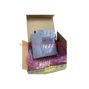
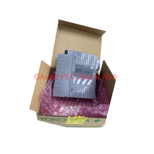
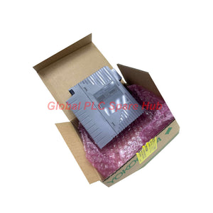
ALF111-S50 Yokogawa ALF111 Series Fieldbus Communication Module
Manufacturer: Yokogawa
Product No.: ALF111-S50
Condition: In stock
Product Type: Fieldbus Communication Module
Product Origin: SG
Payment: T/T, Western Union
Weight: 350g
Shipping port: Xiamen
Warranty: 12 months
Estimate delivery times: 12-26 days (International), 3-6 days (United States).
Return within 30 days of purchase. Duties & taxes are non-refundable.
Guaranteed Safe Checkout
Yokogawa ALF111-S50 FOUNDATION Fieldbus Communication Module
The ALF111-S50 is a Yokogawa FOUNDATION Fieldbus communication module for industrial control system integration. It provides four fieldbus ports, with each port supporting one low-speed voltage-mode segment. The module operates at 31.25 kbps and supports LAS and clock master functions.
Engineers can use the ALF111-S50 to connect field instruments with compatible Yokogawa control system nodes. Its dual-redundancy configuration supports installations requiring improved communication availability. Correct segment planning, device-count verification, and termination settings remain essential during commissioning.
1. Hardware Profile and Operating Limits
| Parameter | Specification | Engineering Relevance |
|---|---|---|
| Manufacturer | Yokogawa | Industrial control and fieldbus integration |
| Model | ALF111-S50 | Complete ordering code |
| Module type | FOUNDATION Fieldbus Communication Module | Field-device communication interface |
| Fieldbus interface | Low-speed voltage mode | FOUNDATION Fieldbus segment communication |
| Number of ports | 4 | Supports four separate segments |
| Segment allocation | 1 segment per port | Four ports do not represent one shared segment |
| Transmission speed | 31.25 kbps | Fieldbus communication rate |
| Control I/O capacity | Maximum 48 points per segment | Observe the specified scanning-cycle conditions |
| Fieldbus device capacity | Maximum 32 units per segment | The ALF111 counts as one unit |
| Communication functions | LAS and clock master | Supports fieldbus link scheduling and time coordination |
| Redundancy | Dual-redundancy configuration supported | Two ALF111 modules can occupy designated adjacent slots in the same node unit |
| Current consumption | 0.5 A or less | Verify node power capacity and total module loading |
| Withstanding voltage | 1500 V AC for 1 minute | Specified isolation withstand capability |
| Approximate weight | 0.40 kg | Useful for handling and inventory planning |
2. Configuration Breakdown — Ordering Code Tree
Complete model: ALF111-S50
-
ALF111 — FOUNDATION Fieldbus Communication Module
- -S — Standard type
- 5 — Without explosion protection
- 0 — Basic type
Ordering guidance: Match the full suffix code against the installed system requirements. The “5” code indicates no explosion protection, so do not select this version for an installation requiring module-level explosion protection.
3. Port Architecture and Segment Planning
| Configuration Item | Specified Limit | Selection or Design Check |
|---|---|---|
| Available fieldbus ports | 4 ports | Map each port to its intended fieldbus segment. |
| Segments per port | 1 segment | Plan device allocation and wiring independently for each segment. |
| Control I/O points | Maximum 48 per segment | Confirm the applicable scanning-cycle configuration. |
| High-speed scanning allocation | Up to 6 I/O points | The specified ER bus configuration supports high- and medium-speed scanning cycles under this condition. |
| Fieldbus devices | Maximum 32 units per segment | Include the ALF111 in the stated unit count. |
| Built-in termination | Switchable terminators | Check segment-end termination against the approved network design. |
Do not treat the 48-point control I/O limit and 32-unit fieldbus limit as interchangeable. They describe different constraints. Verify both limits for each segment before finalizing the instrument list.
4. Compatible Platforms and Typical Applications
The ALF111 supports installation on the following specified Yokogawa node or base-unit families. Confirm the exact hardware variant and slot requirements before ordering.
- ANB10 series
- ANB11 series
- AFV30 series
- AFV40 series
- A2FV50 series
- A2FV70 series
Typical engineering applications include:
- Process instrumentation: Connecting compatible FOUNDATION Fieldbus instruments to a supported Yokogawa control node.
- Distributed control systems: Integrating field-device communication into process control architectures.
- Multi-segment installations: Distributing field instruments across four independently planned fieldbus segments.
- Redundant control configurations: Supporting installations that require two ALF111 modules in designated adjacent slots within the same node unit.
- Plant upgrades and spare replacement: Replacing a matching module while preserving the approved node configuration and fieldbus design.
Actual compatibility depends on the control system model, node hardware, software revision, slot arrangement, and fieldbus configuration. Confirm these details before purchasing a replacement.
5. Installation and Commissioning Checklist
- Verify the node: Confirm that the installed base unit belongs to a supported family and accepts the required module configuration.
- Check the slot plan: Follow the system hardware documentation for module placement, especially in redundant configurations.
- Inspect segment wiring: Confirm terminal connections, cable routing, polarity requirements, and approved segment wiring practices.
- Review termination: Check the switchable built-in terminators against the approved segment topology. Avoid incorrect or duplicate termination.
- Count devices: Include the ALF111 in the maximum 32-unit segment count and separately verify the 48-point control I/O limit.
- Check power capacity: Allow for the specified module current consumption and the total load of the node.
- Validate communications: Confirm that the control system recognizes the module and that expected field devices communicate successfully.
- Test redundancy: Where redundancy is configured, verify module status and changeover behavior using the approved system procedure.
Always isolate equipment and follow site safety procedures before changing wiring or module connections. Use the applicable Yokogawa installation and maintenance documentation for detailed procedures.
6. Communication Diagnostics and Troubleshooting
| Observed Symptom | Checks to Perform | Engineering Consideration |
|---|---|---|
| Field devices fail to communicate | Inspect segment wiring, termination, device power, and device configuration. | Check the affected port and segment before replacing the module. |
| Several devices on one segment become unavailable | Review common wiring points, segment power, and termination settings. | A shared segment fault may affect multiple devices simultaneously. |
| Device capacity exceeds the design limit | Recount all fieldbus units, including the ALF111. | Do not exceed 32 units per segment. |
| Control scanning performance does not meet expectations | Review the configured I/O points and scanning-cycle assignments. | High-speed scanning allocation has specific configuration conditions. |
| Redundant operation does not behave as expected | Check module placement, redundancy configuration, and system status indications. | Confirm the node supports the intended redundant arrangement. |
| Module replacement does not restore communication | Verify the complete model code, hardware compatibility, configuration, and field wiring. | A replacement module cannot correct an unrelated segment or configuration fault. |
Diagnostic capability note: The supplied specifications identify LAS and clock master functions, but do not define a complete onboard diagnostic feature set. Use the host control system's available status information and approved troubleshooting tools. Do not assume specific fault codes, event logs, or diagnostic LEDs without checking the relevant manual.
7. Electrical Isolation and Connection Details
| Item | Specification or Requirement |
|---|---|
| Field-to-system withstand voltage | 1500 V AC for 1 minute |
| Primary-to-secondary withstand voltage | 1500 V AC for 1 minute |
| Channel-to-channel withstand voltage | 1500 V AC for 1 minute |
| External bus connection | Removable pressure-clamp terminal block |
| Termination arrangement | Built-in terminators with on/off switching |
| Terminal board connection | Dedicated cable connection |
Withstand-voltage ratings describe specified insulation test performance. They do not replace grounding, isolation, wiring, or hazardous-area installation requirements.
8. Global PLC Spare HUB's Insight
For the ALF111-S50, the main selection risk is often segment design rather than the nominal communication speed. Engineers should validate the device count, control I/O allocation, termination, and node compatibility together.
The four-port architecture can simplify fieldbus distribution across separate instrument groups. However, each port represents one segment, so capacity must be checked individually rather than combined across the module.
For redundancy projects, confirm the exact adjacent-slot arrangement and host-system support before procurement. A redundant hardware arrangement alone does not prove that the entire communication path has redundant power, wiring, or field devices.
During fault investigation, begin with the affected segment and shared connection points. This approach helps distinguish wiring or termination issues from module, node, and configuration problems.
9. Supply, Warranty, and Shipping
- Product: Yokogawa ALF111-S50 FOUNDATION Fieldbus Communication Module.
- Condition: Confirm the supplied condition and packaging details with the sales team before ordering.
- Warranty: 12-month seller warranty, subject to the agreed sales terms.
- Shipping options: FedEx, UPS, or DHL, subject to destination and service availability.
- Dispatch: Typically within 24–48 hours after order confirmation, subject to stock availability and payment verification.
- Package contents: The module is supplied according to the confirmed order configuration. Additional cables, terminal boards, and accessories are not assumed to be included.
10. Frequently Asked Questions
Q1. How can I confirm whether the ALF111-S50 will fit an existing Yokogawa node?
Check the node model, base-unit variant, available slot, and system hardware revision. Compare them with the official compatibility documentation before ordering.
Q2. Can all four ports share one combined limit of 32 fieldbus devices?
No. The specification states a maximum of 32 units per segment, including the ALF111 as one unit. Calculate the device count separately for each port's segment.
Q3. What information should I provide when requesting a replacement quote?
Provide the full ALF111-S50 code, a clear label photograph, the host node model, and the required quantity. Include the existing module's installation position when available.
Q4. Does the ALF111-S50 guarantee uninterrupted communication during a module failure?
No module specification alone guarantees uninterrupted service. The ALF111 supports a dual-redundancy configuration, but actual continuity depends on system design, configuration, field wiring, and validated changeover behavior.
Q5. What should I check before commissioning a newly installed module?
Verify slot compatibility, segment termination, device counts, node power capacity, and host-system recognition. Then test each segment and any configured redundancy under the site's approved commissioning procedure.
Request a Quote for ALF111-S50
Contact Global PLC Spare HUB to confirm availability, lead time, shipping options, and compatibility for your Yokogawa system. Provide your full model code and application details to help our team assess your requirements.
Tags
Q: Are these parts 100% original and new?
A: Yes. Every component is guaranteed to be 100% original, brand-new, and factory-sealed. We also provide a 12-month comprehensive warranty for your peace of mind.
Q: How fast is the shipping to my country?
A: For in-stock items, we offer same-day dispatch. International express shipping (DHL/FedEx/UPS) typically delivers within 3–5 business days worldwide.
Q: Can I get a formal quotation with shipping costs?
A: Absolutely. Our sales team is ready to provide a detailed Proforma Invoice (PI) including the most competitive shipping rates for your location.
Q: Do you offer discounts for bulk orders?
A: We provide volume-based pricing for large projects or multiple-item orders. Please contact us to get our Best Price Guarantee.
12-Month Comprehensive Warranty
Every part supplied by Global PLC Spare Hub is covered by a 12-month warranty from the date of invoice.
- Coverage: Functional defects and hardware failures under normal operating conditions.
- Commitment: We provide immediate repair, replacement, or a full refund for any verified defective components to minimize your operational downtime.
Returns & Exchange Policy
We offer a 30-day return policy to ensure you receive the exact part your system requires.
- Eligibility: Returns are accepted for uninstalled items in their original, factory-sealed packaging.
- RMA Process: Please contact our support team to obtain a Return Merchandise Authorization (RMA) number before shipping.
- Fast Processing: Refunds or exchanges are processed within 3–5 business days after the returned item passes our technical inspection.
Need Technical Assistance?Not sure if this part is compatible with your system? [Consult our Engineers] before purchasing to ensure 100% compatibility.
People Also Bought


