


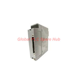
AAI141-H50/K4A00 Yokogawa AAI141 HART Analog Input Module | 16-Channel
Manufacturer: Yokogawa
Product No.: AAI141-H50/K4A00
Condition: In stock
Product Type: Analog Input Module
Product Origin: SG
Payment: T/T, Western Union
Weight: 350g
Shipping port: Xiamen
Warranty: 12 months
Estimate delivery times: 12-26 days (International), 3-6 days (United States).
Return within 30 days of purchase. Duties & taxes are non-refundable.
Guaranteed Safe Checkout
Yokogawa AAI141-H50/K4A00 | 16-Channel HART Analog Input Module
01 — Signal Acquisition Profile
The Yokogawa AAI141-H50/K4A00 is a 16-channel analog input module for industrial process measurement. It accepts 4–20 mA DC signals and supports HART digital communication. The module provides non-isolated inputs and a 10 ms data update period. Its 100 ms step response supports process signal acquisition. Engineers can configure each channel for 2-wire or 4-wire transmitter operation. The K4A00 option provides a KS cable interface adapter. This configuration suits installations that require current-loop measurement and HART-capable field instrumentation.
02 — Technical Specifications
| Parameter | Specification |
|---|---|
| Manufacturer | Yokogawa |
| Model | AAI141-H50/K4A00 |
| Series | AAI141 |
| Product type | Analog input module with HART communication |
| Input channels | 16, non-isolated |
| Input signal | 4–20 mA DC |
| Maximum allowable input current | 27 mA |
| Input resistance, power on | 400 Ω at 20 mA; 1000 Ω at 4 mA |
| Input resistance, power off | 500 kΩ minimum |
| Specified accuracy | ±16 μA |
| Data update period | 10 ms |
| Step response time | 100 ms |
| Transmitter supply at 20 mA | 14.8 V minimum |
| Transmitter supply at 0 mA | 26.4 V maximum |
| Transmitter supply current limit | 27 mA |
| Transmitter configuration | 2-wire or 4-wire, selected per channel using setting pins |
| Temperature drift | ±16 μA per 10°C |
| Maximum 5 V DC consumption | 310 mA |
| Maximum 24 V DC consumption | 450 mA |
| HART communication | Available |
| External connection | Pressure-clamp terminal, KS cable, or MIL connector cable |
| Approximate weight | 0.2 kg |
The supplied specifications do not identify resolution, linearity, or a complete operating temperature range. Check the applicable Yokogawa hardware manual for these values.
03 — Ordering Code: Configuration Breakdown
AAI141-H50/K4A00
AAI141 — Identifies the analog input module family. H — Specifies digital communication with the HART protocol. 5 — Specifies the configuration without explosion protection. 0 — Identifies the basic type. K4A00 — Specifies the KS cable interface adapter.
**Selected configuration at a glance**
| Configuration feature | Selected value |
|---|---|
| Measurement type | 4–20 mA current input |
| Channel count | 16 |
| Input isolation | Non-isolated |
| Digital communication | HART |
| Explosion protection | Not included |
| Connection interface | KS cable interface adapter |
04 — Measurement Performance and HART Capability
The module converts analog current-loop signals into process values for the control system.
- Current range: Standard 4–20 mA instrumentation signals.
- Accuracy: Specified measurement accuracy of ±16 μA.
- Acquisition interval: Input data updates every 10 ms.
- Step response: The specified response time is 100 ms.
- HART support: Enables digital communication with compatible HART instruments.
- Channel configuration: Engineers select 2-wire or 4-wire operation individually.
The 10 ms update period does not mean every field instrument responds within 10 ms. The specified step response is 100 ms. HART communication availability does not establish support for every HART command or asset-management feature. Confirm the supported functions in the system documentation.
05 — Field Wiring and Installation
The K4A00 configuration identifies a KS cable interface adapter. The module also supports pressure-clamp terminals and MIL connector cables. **Installation sequence**
- Confirm the full model code and control system compatibility.
- Review the approved module installation position and connection interface.
- Isolate equipment according to site electrical safety procedures.
- Set each channel for the connected transmitter's wiring type.
- Verify the field instrument's current output and supply requirements.
- Connect the approved cable or terminal assembly.
- Check signal polarity and channel identification.
- Configure the engineering range in the control system.
- Test representative channels using a calibrated current source.
The module uses non-isolated inputs. Review grounding and common-mode conditions before connecting instruments with different electrical references.
06 — Application Fit: Where Engineers Use It
The AAI141-H50/K4A00 suits process systems that collect analog measurements from compatible transmitters.
- Pressure monitoring: Acquire pressure transmitter signals from process lines and vessels.
- Flow measurement: Read current outputs from compatible flow transmitters.
- Level instrumentation: Collect tank and vessel level measurements.
- Temperature monitoring: Acquire signals from transmitters that convert temperature into 4–20 mA.
- Process diagnostics: Support HART communication with compatible field instruments.
- Control cabinet integration: Connect multiple current-loop instruments through the specified interface.
Check the control system's supported I/O architecture before assigning the module to a particular rack or node.
07 — Commissioning Example: Flow Transmitter
Consider a flow transmitter configured for 0–100 m³/h and a 4–20 mA output.
| Loop current | Expected flow |
|---|---|
| 4 mA | 0 m³/h |
| 12 mA | 50 m³/h |
| 20 mA | 100 m³/h |
During commissioning, inject these current values and compare the displayed flow against the expected values. Check transmitter scaling and control-system engineering units if readings differ. For HART instruments, verify digital communication separately. A correct analog reading does not automatically confirm successful HART communication.
08 — Diagnostics and Maintenance
The supplied specifications confirm HART availability. They do not specify particular onboard alarms, diagnostic indicators, or fault codes. Use these field checks to isolate common signal problems:
- Low or zero reading: Measure loop current and inspect transmitter power, polarity, and continuity.
- Incorrect process value: Check channel scaling, instrument range, and configured engineering units.
- Unstable signal: Inspect grounding, shielding, cable routing, and electrical noise sources.
- HART communication failure: Confirm instrument compatibility, wiring, and communication configuration.
- Multiple channel deviations: Check common wiring references and system configuration.
- Periodic maintenance: Inspect connections and compare measurements with calibration records.
Use approved system diagnostic tools to identify module-specific status information.
09 — Compatibility and Selection Checklist
Before purchasing the AAI141-H50/K4A00, confirm:
- Control system and I/O subsystem compatibility.
- Supported AAI141 module revision and installation position.
- Required KS cable interface adapter.
- Field transmitter output range and wiring type.
- HART communication requirements and supported functions.
- Grounding arrangements for non-isolated inputs.
- Environmental and hazardous-area requirements.
The suffix specifies no explosion protection. Do not assume suitability for hazardous locations without checking the site's approval requirements.
10 — Global PLC Spare HUB's Insight
The AAI141-H50/K4A00 combines 16 current inputs with HART communication. Engineers should assess both analog acquisition and digital instrument communication during system planning. For example, a maintenance team may replace a pressure transmitter and retain its existing loop wiring. The team should verify the channel's 2-wire or 4-wire setting, current scaling, and HART compatibility before commissioning. Because the inputs are non-isolated, engineers should also review grounding and electrical reference conditions. This check can help prevent avoidable signal instability across connected instruments.
11 — Packaging, Warranty, and Shipping
- Product: Yokogawa AAI141-H50/K4A00 analog input module.
- Packaging: Protective packaging for industrial electronic equipment.
- Accessories: Confirm the KS cable interface adapter and other included items with the supplier.
- Warranty: 12-month warranty, subject to applicable sales terms.
- Shipping options: FedEx, UPS, and DHL.
- Dispatch target: 24–48 hours after order confirmation and stock verification.
12 — Frequently Asked Questions
- Does HART support allow remote configuration of every connected transmitter? Not necessarily. The module supports HART communication, but available commands and configuration functions depend on the instrument and control system.
- 2. Can I connect a transmitter with a 0–20 mA output? The specified rated input signal is 4–20 mA. Confirm the applicable hardware limits and system configuration before using another signal range.
- 3. What does non-isolated input mean for cabinet wiring? The inputs do not provide individual channel isolation. Review shared electrical references, grounding, and transmitter connections to avoid unwanted current paths.
- 4. How should I verify the KS cable interface during replacement? Check the installed adapter designation, cable type, connector arrangement, and control system documentation. Do not assume that similar-looking cables share the same pinout.
- 5. Should I choose this model when analog measurement accuracy is the main requirement? Compare the specified ±16 μA accuracy with the application's measurement tolerance. Also review temperature drift, transmitter accuracy, signal conditioning, and the complete measurement chain.

Tags
Q: Are these parts 100% original and new?
A: Yes. Every component is guaranteed to be 100% original, brand-new, and factory-sealed. We also provide a 12-month comprehensive warranty for your peace of mind.
Q: How fast is the shipping to my country?
A: For in-stock items, we offer same-day dispatch. International express shipping (DHL/FedEx/UPS) typically delivers within 3–5 business days worldwide.
Q: Can I get a formal quotation with shipping costs?
A: Absolutely. Our sales team is ready to provide a detailed Proforma Invoice (PI) including the most competitive shipping rates for your location.
Q: Do you offer discounts for bulk orders?
A: We provide volume-based pricing for large projects or multiple-item orders. Please contact us to get our Best Price Guarantee.
12-Month Comprehensive Warranty
Every part supplied by Global PLC Spare Hub is covered by a 12-month warranty from the date of invoice.
- Coverage: Functional defects and hardware failures under normal operating conditions.
- Commitment: We provide immediate repair, replacement, or a full refund for any verified defective components to minimize your operational downtime.
Returns & Exchange Policy
We offer a 30-day return policy to ensure you receive the exact part your system requires.
- Eligibility: Returns are accepted for uninstalled items in their original, factory-sealed packaging.
- RMA Process: Please contact our support team to obtain a Return Merchandise Authorization (RMA) number before shipping.
- Fast Processing: Refunds or exchanges are processed within 3–5 business days after the returned item passes our technical inspection.
Need Technical Assistance?Not sure if this part is compatible with your system? [Consult our Engineers] before purchasing to ensure 100% compatibility.
People Also Bought


