


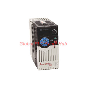
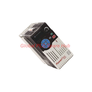
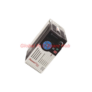
25B-D030N104 PowerFlex 520 Series Allen-Bradley Variable Frequency Drive
Manufacturer: Allen-Bradley
Product No.: 25B-D030N104
Condition: In stock
Product Type: AC Drive
Product Origin: USA
Payment: T/T, Western Union
Weight: 4190g
Shipping port: Xiamen
Warranty: 12 months
Estimate delivery times: 12-26 days (International), 3-6 days (United States).
Return within 30 days of purchase. Duties & taxes are non-refundable.
Guaranteed Safe Checkout
25B-D030N104 | PowerFlex 525 Drive at a Glance
The Allen-Bradley 25B-D030N104 is a three-phase AC adjustable-frequency drive from the PowerFlex 525 family. It belongs to the PowerFlex 520-series platform and combines motor speed control, embedded EtherNet/IP communication, and Safe Torque Off (STO).
This Frame D drive delivers 15.0 kW (20 HP) in Normal Duty or 11.0 kW (15 HP) in Heavy Duty. Its continuous output current is 30.0 A. The unit supports panel mounting and uses an IP20 / NEMA/UL Type Open enclosure.
| Manufacturer | Allen-Bradley / Rockwell Automation |
| Catalog Number | 25B-D030N104 |
| Product Family | PowerFlex 525 |
| Platform | PowerFlex 520 Series |
| Product Type | AC Adjustable-Frequency Drive |
| Input Supply | 380–480V AC, 3-phase, 47–63 Hz |
| Continuous Output Current | 30.0 A |
| Normal Duty Rating | 15.0 kW / 20 HP |
| Heavy Duty Rating | 11.0 kW / 15 HP |
| Frame Size | Frame D |
| Communication | Embedded EtherNet/IP and RS-485 DSI |
| Safety Function | Embedded Safe Torque Off (STO) |
| Enclosure | IP20 / NEMA/UL Type Open |
| Integral EMC Filter | Not included |
01 | Motor Power and Operating Capability
Drive selection should start with the motor nameplate and the actual load profile. The 25B-D030N104 provides two published operating ratings. Select the applicable rating according to the required duty classification.
| Normal Duty Output Power | 15.0 kW (20 HP) |
| Heavy Duty Output Power | 11.0 kW (15 HP) |
| Continuous Output Current | 30.0 A |
| Output Voltage | 0–460V AC, three-phase rating block |
| Output Frequency | 0–500 Hz, programmable |
| PWM Carrier Frequency | 2–16 kHz, programmable |
| Published Current Rating Basis | 4 kHz carrier frequency |
| Typical Efficiency | 97.5% |
| Displacement Power Factor | 0.98 across the speed range |
| Total Power Loss | 387 W |
Motor control methods:
- Sinusoidal pulse-width modulation (PWM)
- Volts/Hertz control
- Sensorless Vector Control (SVC)
- SVC Economizer
- Closed-Loop Velocity Vector Control
- Surface-mount and interior permanent-magnet motor control, with or without encoder
The drive supports four independently programmable acceleration and deceleration times. Each setting ranges from 0 to 600 seconds, in 0.01-second increments.
Available stop modes include Ramp, Coast, DC Brake, and Ramp to Stop. Heavy Duty overload capability reaches 150% of rated output current for 60 seconds and 180% for 3 seconds. The drive also supports a programmable 200% overload setting.
Selection note: Confirm the motor current, load inertia, starting torque, and duty classification before choosing the drive. Do not select by horsepower alone.
02 | Control Architecture and I/O Connectivity
The PowerFlex 525 combines local drive control with flexible field wiring. Its standard control module includes digital, analog, relay, and opto-isolated output interfaces.
| Digital Inputs | 1 dedicated Stop input plus 6 programmable inputs |
| Digital Input Logic | SRC or SNK, 18–24V DC ON / 0–6V DC OFF according to mode |
| Pulse Train Input | 1 input, shared with a programmable digital input; 0–100 kHz |
| Analog Inputs | 2 isolated inputs: -10 to +10V DC and 4–20 mA |
| Analog Input Resolution | 10-bit |
| Relay Outputs | 1 Form A and 1 Form B, programmable |
| Opto Outputs | 2 programmable outputs, 30V DC, 50 mA |
| Analog Output | 0–10V or 4–20 mA, non-isolated |
| Encoder Feedback | Incremental dual-channel interface |
The analog inputs accept voltage or current references. Their input impedance is 100 kΩ for voltage and 250 Ω for current. The analog output provides 10-bit resolution.
The encoder interface supplies 12V DC at 250 mA. It supports quadrature feedback and a maximum input frequency of 250 kHz DC.
Practical wiring consideration: Check the selected SRC/SNK input mode before connecting field devices. Confirm analog signal type and common-reference wiring against the control circuit drawing.
03 | Network Integration and Functional Safety
The 25B-D030N104 is a PowerFlex 525 model with an embedded EtherNet/IP port. It also provides an RS-485 DSI port for serial communication and multi-drive applications.
| Embedded Network | EtherNet/IP, RJ45 |
| Serial Interface | RS-485 DSI multi-drop |
| Serial Protocol Support | Modbus RTU over the RS-485 interface |
| Modbus Functions | 03 Read Holding Registers; 06 Write Single Register; 16 Write Multiple Registers |
| Expansion Options | DeviceNet, dual-port EtherNet/IP, PROFIBUS DP-V1, PROFINET IO |
Optional communication adapters support integration with different automation networks. The dual-port EtherNet/IP adapter, 25-COMM-E2P, supports Device Level Ring (DLR) topologies.
The embedded Safe Torque Off (STO) function provides a safety-rated means of preventing motor torque generation. The published functional safety rating is Category 3, PLd, and SIL 2, certified by TÜV Rheinland.
External safety components can be combined with the drive's STO function to achieve higher system-level safety targets, subject to the complete safety design and validation.
Engineering note: STO is a functional safety feature. It does not replace electrical isolation or lockout/tagout procedures during maintenance.
04 | Installation Conditions and Cabinet Planning
This model uses a Frame D, IP20 open-style enclosure. Install it inside a suitable electrical cabinet with adequate ventilation and protection against environmental contamination.
| Mounting | Panel mounting; DIN rail or screw mounting for Frames A–D |
| Permitted Orientation | Vertical, vertical zero-stacking, or horizontal, subject to frame and temperature restrictions |
| Protection Rating | IP20 / NEMA/UL Type Open |
| Operating Temperature | -20 to +50°C without derating for standard vertical mounting |
| Extended Temperature | Up to +60°C with derating; up to +70°C with the applicable fan kit and mounting conditions |
| Storage Temperature | -40 to +85°C for Frame D |
| Relative Humidity | 0–95%, non-condensing |
| Maximum Altitude Without Derating | 1,000 m |
| Maximum Altitude With Derating | 4,000 m, subject to current derating requirements |
| Frame D Dimensions (H × W × D) | 260 × 130 × 212 mm |
| Frame D Weight | 3.9 kg |
Temperature limits depend on mounting orientation and zero-stacking arrangement. Check the Rockwell Automation ambient-temperature table before finalizing cabinet spacing.
Keep the drive away from atmospheres containing volatile or corrosive gases, vapors, or dust. Maintain the specified clearances and airflow around the heatsink.
05 | Power Wiring, EMC, and Protection Requirements
The catalog number specifies a drive without an integral EMC filter. Where the installation requires EMC compliance, assess the motor cable length, grounding arrangement, and applicable emission category.
- Input supply: 380–480V AC, three-phase, 47–63 Hz.
- Permitted input voltage: 323–528V AC.
- Maximum input current: 33.0 A.
- Input branch-circuit rating: 30.2 kVA.
- Maximum short-circuit rating: 100,000 A symmetrical, subject to the installed protective device rating.
- IEC fuse selection: 45 A minimum and 70 A maximum, according to the published protection table.
- UL fuse classes: Class CC, J, or T/70, according to the published protection table.
The external EMC line filter listed for a 100 m motor cable application is 25-RF033-DL. The technical data does not publish a 150 m filter catalog number for this particular rating.
For Frame D installations, the optional 25-JBAD kit provides an IP30 / NEMA Type 1 / UL Type 1 enclosure conversion. This kit does not make the drive suitable for every outdoor or hazardous environment.
Use the published branch-circuit protection tables to select fuses or circuit breakers. Do not substitute protective devices based only on the drive's 30 A output rating.
06 | Catalog Number and Hardware Identification
The catalog number identifies the drive family, voltage class, current rating, enclosure, interface, EMC filter, and braking configuration.
| 25B | PowerFlex 525 drive family |
| D | 380–480V AC voltage class |
| 030 | 30.0 A rated output-current designation |
| N | IP20 NEMA/UL Type Open enclosure |
| 1 | Standard interface module |
| 0 | No integral EMC filter |
| 4 | Standard braking configuration with integral brake IGBT |
The integral brake IGBT provides the drive-side switching hardware for dynamic braking. An appropriately selected external brake resistor is required when the application uses dynamic braking.
The 25B prefix identifies the PowerFlex 525. The 25A prefix identifies the PowerFlex 523, which does not provide the same feature set. Confirm the exact catalog number before ordering replacement hardware or communication accessories.
07 | Recommended Accessories and Replacement Considerations
| 25-JBAD | Frame D IP30 / NEMA Type 1 enclosure kit |
| 25-FAN1-FD | Frame D heatsink replacement fan |
| 25-FAN1-70C | Control module fan kit for applicable high-temperature or horizontal-mounting conditions |
| 25-RF033-DL | External EMC line filter listed for the 100 m motor cable application |
| 25-ENC-1 | Incremental encoder input option board |
| 25-COMM-E2P | Dual-port EtherNet/IP communication adapter |
| 25-COMM-D | DeviceNet communication adapter |
| 25-COMM-P | PROFIBUS DP-V1 communication adapter |
| 25-COMM-PNET2P | PROFINET IO communication adapter |
| 22-SCM-232 | RS-485 to RS-232 serial converter module |
| 1203-USB | USB converter module for drive configuration and software connection |
Important encoder warning: Use only the 25-ENC-1 encoder option with the PowerFlex 525. Rockwell Automation warns that an incorrect encoder card, such as the PowerFlex 527 25-ENC-2, can damage the drive.
Accessory selection depends on the installed hardware, communication architecture, mounting arrangement, and application requirements. Confirm compatibility before ordering an option kit.
08 | Commissioning and Maintenance Checkpoints
- Verify the supply: Measure the incoming three-phase voltage and confirm that it falls within the 323–528V AC input range.
- Check motor data: Enter the motor nameplate values and confirm the selected Normal Duty or Heavy Duty rating.
- Inspect grounding: Verify protective earth connections, cable routing, and shield termination.
- Configure control inputs: Confirm SRC or SNK logic before applying external digital signals.
- Check analog references: Match the controller output to the selected voltage or current input configuration.
- Test communication: Verify the EtherNet/IP address or RS-485 settings and confirm controller-to-drive data exchange.
- Validate safety: Test the STO circuit and complete the required machine-level safety validation.
- Monitor thermal conditions: Check cabinet airflow, heatsink fan operation, and ambient temperature during loaded operation.
For maintenance, inspect power terminals, cooling passages, fan condition, and cable insulation. Review fault history before replacing the drive. Record parameter settings and communication configuration before carrying out a replacement.
09 | Certifications and Application Compliance
The PowerFlex 525 family documentation lists the following approvals and compliance information applicable to this drive family:
- Functional Safety: TÜV Rheinland type approval; ISO 13849-1 Category 3, PLd and SIL 2 for the embedded STO function.
- ATEX: TÜV 12 ATEX 7199 X for Group II Category (2) GD applications with ATEX-approved motors.
- UKEX: TÜV 21 UKEX 7031 X.
- Agency approvals: c-UL-us Listed to UL 508C, CSA C22.2 No. 274, UL 61800-5-1, and CSA C22.2 No. 274-17.
- Regional compliance: CE, UKCA, RCM, KC, and RoHS.
- Additional qualifications: SEMI F47, IEC 61000-4-11, IEC 61000-4-34, and seismic qualification to AC156.
- Marine approval: Lloyd's Register Type Approval Certificate 12/10068(E1).
Confirm the complete installation requirements before using the drive in an ATEX application. The published ATEX approval specifies use with approved motors and the stated equipment category.
10 | Frequently Asked Questions
Q1: How should engineers choose between the 20 HP Normal Duty and 15 HP Heavy Duty ratings?
A: Start with the motor nameplate current and the driven machine's torque profile. Conveyors, mixers, and other high-torque loads may require the Heavy Duty rating. A higher motor horsepower label does not automatically establish suitability. Check acceleration demand, overload duration, and operating cycles against the drive's published ratings.
Q2: What should be checked when an existing PowerFlex 525 installation experiences communication interruptions?
A: Check the EtherNet/IP cable, connector condition, network addressing, and controller configuration first. For RS-485 Modbus RTU, verify wiring polarity, network termination, baud rate, and register addressing. Some Modbus masters use one-based addressing, so a register offset may be necessary. Confirm the addressing convention before changing drive parameters.
Q3: Can this drive be installed in a cabinet without an additional EMC filter?
A: The drive has no integral EMC filter. Whether an external filter is necessary depends on the installation's emission category, motor cable length, and applicable standards. For the published 100 m cable application, Rockwell lists the 25-RF033-DL filter. Check the installation requirements rather than assuming every cabinet needs the same filter.
Q4: What is a common mistake when adding encoder feedback to this model?
A: Selecting an encoder option intended for another PowerFlex family can cause hardware damage. This drive requires the 25-ENC-1 option. Before installation, confirm the option-board catalog number, encoder supply voltage, output type, and wiring arrangement. Do not use the PowerFlex 527 25-ENC-2 card.
Q5: What should maintenance teams investigate before replacing a drive after an overtemperature or thermal fault?
A: Check cabinet temperature, airflow obstruction, heatsink fan operation, mounting orientation, and drive loading. Zero-stacking and horizontal mounting can change the permitted ambient-temperature limits. Also review the motor current and operating cycle. Correcting ventilation or load conditions may prevent a repeat fault after replacement.
11 | Product Identification and Ordering
When requesting a quotation or replacement, provide the complete catalog number 25B-D030N104. Also confirm the input voltage, motor rating, enclosure requirements, communication interface, and installed option cards.
For replacement projects, compare the existing drive's parameter configuration and accessory hardware before installation. This helps reduce commissioning changes and avoids incompatible option-card selections.
Tags
Q: Are these parts 100% original and new?
A: Yes. Every component is guaranteed to be 100% original, brand-new, and factory-sealed. We also provide a 12-month comprehensive warranty for your peace of mind.
Q: How fast is the shipping to my country?
A: For in-stock items, we offer same-day dispatch. International express shipping (DHL/FedEx/UPS) typically delivers within 3–5 business days worldwide.
Q: Can I get a formal quotation with shipping costs?
A: Absolutely. Our sales team is ready to provide a detailed Proforma Invoice (PI) including the most competitive shipping rates for your location.
Q: Do you offer discounts for bulk orders?
A: We provide volume-based pricing for large projects or multiple-item orders. Please contact us to get our Best Price Guarantee.
12-Month Comprehensive Warranty
Every part supplied by Global PLC Spare Hub is covered by a 12-month warranty from the date of invoice.
- Coverage: Functional defects and hardware failures under normal operating conditions.
- Commitment: We provide immediate repair, replacement, or a full refund for any verified defective components to minimize your operational downtime.
Returns & Exchange Policy
We offer a 30-day return policy to ensure you receive the exact part your system requires.
- Eligibility: Returns are accepted for uninstalled items in their original, factory-sealed packaging.
- RMA Process: Please contact our support team to obtain a Return Merchandise Authorization (RMA) number before shipping.
- Fast Processing: Refunds or exchanges are processed within 3–5 business days after the returned item passes our technical inspection.
Need Technical Assistance?Not sure if this part is compatible with your system? [Consult our Engineers] before purchasing to ensure 100% compatibility.
People Also Bought


