


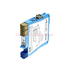

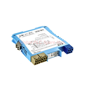
MTL5514 MTL 5500 Single-Channel NAMUR Switch Isolator
Manufacturer: MTL
Product No.: MTL5514
Condition: En stock
Product Type: Switch Isolator
Product Origin: EN
Payment: T/T, Western Union
Weight: 350g
Shipping port: Xiamen
Warranty: 12 months
Tiempo estimado de entrega: 12-26 días (Internacional), 3-6 días (Estados Unidos).
Devolución dentro de los 30 días siguientes a la compra. Los aranceles e impuestos no son reembolsables.
Pago Seguro Garantizado
Product Overview
The MTL5514 is a single-channel intrinsically safe switch isolator from the MTL 5500 Series. It interfaces compatible NAMUR proximity detectors and contact inputs with safe-area relay circuits.
The module transfers field switching signals to control and monitoring systems. It also supports selectable line fault detection (LFD) for compatible input circuits. Three LED indicators help technicians check power, channel status, and detected line faults.
- Model: MTL5514
- Series: MTL 5500
- Function: Intrinsically safe switch isolation
- Input: One NAMUR proximity detector channel or compatible contact input
- Output: Changeover relay contacts
- Diagnostic feature: Selectable open-circuit and short-circuit detection
Technical Specifications
| Parameter | Specification |
|---|---|
| Brand | MTL |
| Model | MTL5514 |
| Product Series | MTL 5500 Series |
| Product Type | Intrinsically Safe Switch Isolator |
| Number of Channels | 1 |
| Input Standard | BS EN 60947-5-6:2001 |
| Input Device | Compatible NAMUR proximity detector or contact input |
| Sensor Supply | 7–9 V DC through 1 kΩ ±10% |
| Channel Response Time | 10 ms maximum |
| Output Type | Single-pole changeover relay contacts |
| Maximum Current Consumption | 25 mA at 24 V DC |
| Power Dissipation | 0.6 W at 24 V DC |
| Safe-Area AC Contact Rating | 250 V AC, 2 A, cos φ > 0.7 |
| Safe-Area DC Contact Rating | 40 V DC, 2 A, resistive load |
| Zone 2 Contact Rating | 35 V, 2 A, 100 VA |
| Intrinsic Safety Output Voltage | Uo = 10.5 V |
| Intrinsic Safety Output Current | Io = 14 mA |
| Intrinsic Safety Output Power | Po = 37 mW |
| Maximum External Voltage Parameter | Um = 253 V RMS or DC |
| Operating Temperature | Confirm the applicable manufacturer datasheet |
| Dimensions and Weight | Confirm the applicable manufacturer datasheet |
Input Switching Characteristics
The MTL5514 evaluates input current and resistance to determine the channel state. Its nominal hysteresis helps limit unstable switching around the threshold.
| Input Condition | Specified Response |
|---|---|
| Input current above 2.1 mA | Output contacts close in normal phase |
| Input resistance below 2 kΩ | Output contacts close under the specified normal-phase conditions |
| Input current below 1.2 mA | Output contacts open in normal phase |
| Input resistance above 10 kΩ | Output contacts open under the specified normal-phase conditions |
| Nominal Hysteresis | 200 µA, approximately 650 Ω |
These values describe the supplied normal-phase specifications. Confirm the selected operating mode and field circuit before commissioning.
Line Fault Detection
The MTL5514 supports user-selectable line fault detection through switches on the side of the unit. When configured correctly, LFD identifies specified open-circuit and short-circuit conditions.
| Diagnostic Condition | Threshold or Response |
|---|---|
| Open-circuit alarm activates | Input current below 50 µA |
| Open-circuit alarm clears | Input current above 250 µA |
| Short-circuit alarm activates | Input resistance below 100 Ω |
| Short-circuit alarm clears | Input resistance above 360 Ω |
| Line fault indication | Red LED illuminates |
| Line fault relay | Energises when an input line fault is detected |
| Channel output relay | De-energises when an input line fault is detected |
Contact input resistor requirements:
- Install a 500 Ω to 1 kΩ resistor in series with the switch.
- Install a 20 kΩ to 25 kΩ resistor in parallel with the switch.
- Configure the side switches according to the required LFD operating mode.
- Verify the manufacturer's wiring diagram before energising the circuit.
Incorrect resistor values can affect fault discrimination. Confirm the input wiring and configuration during commissioning.
LED Indicators and Diagnostic Functions
| LED Colour | Indication | Recommended Check |
|---|---|---|
| Green | Power indication | Check the DC supply if the expected indication is absent. |
| Yellow | Channel output relay energised | Compare the LED state with the field input. |
| Red | Line fault detected | Check cable continuity, input resistance, and LFD resistors. |
These indicators help technicians narrow down field wiring and switching problems. They do not independently identify every possible failure.
Hazardous-Area Compatibility
| Installation Item | Specified Classification |
|---|---|
| Switch location | Zone 0, IIC, T6 |
| North American switch location | Division 1, Group A |
| Proximity detector location | Zone 0, IIC, T4–T6, subject to suitable certification |
| North American proximity detector location | Division 1, Group A |
| Maximum external voltage parameter | Um = 253 V RMS or DC |
These classifications reflect the supplied product information. They do not replace the applicable certificates or installation control drawings. Verify the complete system approval before use in a hazardous area.
Installation Guide
- Confirm the complete model number and application requirements.
- Isolate the power supply before wiring the module.
- Follow the site's hazardous-area installation procedures.
- Mount the module according to the manufacturer's instructions.
- Connect the compatible NAMUR detector or contact input.
- Wire the relay contacts to the intended PLC, DCS, or alarm circuit.
- Set the LFD switches according to the application requirements.
- Install the specified resistors when contact inputs use LFD.
- Verify terminal assignments and wiring against the correct diagram.
- Apply the specified supply and test channel and fault indications.
Installation note: Do not infer terminal numbers or polarity from the model designation. Always use the manufacturer's wiring diagram for the installed hardware.
Commissioning and Maintenance
- Power verification: Confirm the green LED indicates the expected power condition.
- Input verification: Operate the field sensor and observe the yellow LED.
- Relay verification: Confirm the output contacts change state as required.
- LFD verification: Test open-circuit and short-circuit detection using an approved procedure.
- Control-system verification: Confirm the PLC or DCS receives the intended signal.
- Preventive maintenance: Inspect terminals, wiring, and configuration records during scheduled checks.
Never introduce a fault into a live process without an approved test plan. Apply the required bypass controls and interlock procedures before testing.
Typical Industrial Applications
- Oil and gas: Interface compatible proximity detectors for valve-position feedback.
- Chemical processing: Transfer discrete sensor signals from classified areas to safe-area control systems.
- Power generation: Monitor auxiliary equipment positions and operating states.
- Tank farms: Interface suitable contact signals for valve and process status monitoring.
- Industrial automation: Connect compatible field switches to PLC and DCS relay circuits.
- Hazardous-area machinery: Support approved switching and line fault monitoring arrangements.
Application suitability depends on the sensor, area classification, control drawing, wiring, and output load.
Global PLC Spare HUB's Insight
For maintenance teams, the MTL5514 combines relay-based switching with practical LED diagnostics. Engineers should verify the input thresholds before testing the complete process interlock.
Field example: Valve-position feedback failure
A valve limit switch fails to change the PLC input after maintenance. The technician checks the green power LED, field wiring, sensor operation, and yellow channel LED. The technician then measures the input signal and verifies the relay contacts.
Field example: Unexpected line fault alarm
A line fault alarm appears after a contact switch cable replacement. The technician checks cable continuity and resistor values before replacing the isolator. This sequence helps distinguish wiring errors from potential module faults.
These examples describe practical troubleshooting methods. Actual diagnostic results depend on the installation and configured operating mode.
Compatibility and Selection Guide
- Input type: Confirm NAMUR or supported contact-input compatibility.
- Hazardous-area requirements: Check the complete system certificates and control drawings.
- Output load: Verify AC, DC, resistive, and inductive switching requirements.
- Line fault detection: Confirm whether LFD is required and whether the field wiring supports it.
- Power supply: Verify the supply requirements and installation arrangement.
- Replacement selection: Compare the full model number, terminal arrangement, ratings, and required functions.
Do not select a replacement based only on channel count or series name. Electrical characteristics and hazardous-area requirements must also match.
Packaging, Shipping, and Warranty
- Product: MTL5514 intrinsically safe switch isolator.
- Series: MTL 5500 Series.
- Package contents: One module, subject to the confirmed order configuration.
- Accessories: Included only when specified in the order confirmation.
- Shipping methods: FedEx, UPS, and DHL, subject to destination and service availability.
- Dispatch target: 24–48 hours after order confirmation, subject to stock availability and processing.
- Warranty: 12 months, subject to the seller's written warranty terms.
Please confirm stock, shipping timing, included accessories, and warranty coverage before placing your order.
Frequently Asked Questions
1. What is the main function of the MTL5514?
The MTL5514 interfaces compatible NAMUR proximity detectors or contact inputs with relay-based control circuits. It also supports selectable line fault detection for suitable input configurations.
2. Can the MTL5514 detect a broken sensor cable?
Yes, when LFD is enabled and the input circuit is configured correctly. Contact inputs require the specified series and parallel resistors. Verify the LED and fault relay response through an approved test.
3. Why might the channel output fail to energise?
Check the power supply, input wiring, sensor condition, input current, and selected operating mode. Review the LFD indication and downstream circuit before concluding that the module has failed.
4. What should engineers check before ordering a replacement?
Compare the complete model number, input type, relay ratings, terminal arrangement, LFD requirements, and hazardous-area documentation. Use the installed module's markings and applicable manufacturer documentation.
5. Can the MTL5514 directly switch a motor or solenoid?
Do not assume suitability from the contact rating alone. Check inrush current, inductive load characteristics, and suppression requirements. Use a suitably rated interposing relay or contactor when necessary.
6. How can technicians distinguish wiring faults from module faults?
Start with the power LED and field input signal. Then inspect the channel LED, fault LED, and relay contacts. Measure the field circuit and verify LFD resistors before replacing the module.
7. What information should buyers provide when requesting a quotation?
Provide the complete model number, required quantity, delivery destination, and application details. Include certification requirements and nameplate photos when available. Ask for current stock, dispatch timing, and warranty terms.
Request a Quote
Contact Global PLC Spare HUB for pricing, availability, and technical information about the MTL5514 MTL 5500 Series Intrinsically Safe Switch Isolator.
Please provide the required quantity, delivery destination, and application details. Our team can help review product compatibility and available shipping options before order confirmation.

Tags
P: ¿Son estas piezas 100% originales y nuevas?
R: Sí. Cada componente está garantizado como 100% original, completamente nuevo y sellado de fábrica. También ofrecemos una garantía integral de 12 meses para su tranquilidad.
P: ¿Qué tan rápido es el envío a mi país?
R: Para artículos en stock, ofrecemos envío el mismo día. El envío exprés internacional (DHL/FedEx/UPS) generalmente entrega en un plazo de 3 a 5 días hábiles en todo el mundo.
P: ¿Puedo obtener una cotización formal con los costos de envío?
R: Absolutamente. Nuestro equipo de ventas está listo para proporcionar una factura proforma (PI) detallada que incluya las tarifas de envío más competitivas para su ubicación.
P: ¿Ofrecen descuentos por pedidos al por mayor?
R: Ofrecemos precios basados en el volumen para proyectos grandes o pedidos de varios artículos. Póngase en contacto con nosotros para obtener nuestra Garantía de Mejor Precio.
Garantía Integral de 12 Meses
Cada pieza suministrada por Global PLC Spare Hub está cubierta por una garantía de 12 meses a partir de la fecha de la factura.
- Cobertura: Defectos funcionales y fallos de hardware bajo condiciones normales de funcionamiento.
- Compromiso: Ofrecemos reparación, reemplazo o un reembolso completo inmediato para cualquier componente defectuoso verificado, para minimizar su tiempo de ininactividad operativa.
Política de Devoluciones y Cambios
Ofrecemos una política de devolución de 30 días para asegurar que reciba la pieza exacta que su sistema requiere.
- Elegibilidad: Se aceptan devoluciones de artículos sin instalar en su embalaje original sellado de fábrica.
- Proceso de RMA: Póngase en contacto con nuestro equipo de soporte para obtener un número de Autorización de Devolución de Mercancía (RMA) antes del envío.
- Procesamiento Rápido: Los reembolsos o cambios se procesan dentro de 3 a 5 días hábiles después de que el artículo devuelto pasa nuestra inspección técnica.
¿Necesita Asistencia Técnica? ¿No está seguro de si esta pieza es compatible con su sistema? [Consulte a nuestros Ingenieros] antes de comprar para asegurar una compatibilidad del 100%.
La gente también compró


