


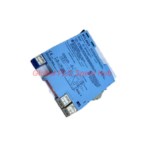
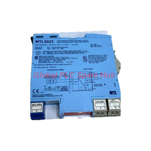
MTL5023 Solenoid Driver | MTL5000 Series Line Fault Detection
Manufacturer: MTL
Product No.: MTL5023
Condition: En stock
Product Type: Solenoid Driver
Product Origin: EN
Payment: T/T, Western Union
Weight: 200g
Shipping port: Xiamen
Warranty: 12 months
Tiempo estimado de entrega: 12-26 días (Internacional), 3-6 días (Estados Unidos).
Devolución dentro de los 30 días siguientes a la compra. Los aranceles e impuestos no son reembolsables.
Pago Seguro Garantizado
Product Overview
The MTL5023 is a powered solenoid and alarm driver from the MTL5000 series. It interfaces safe-area control signals with low-power devices in hazardous areas.
The module accepts a volt-free contact or logic signal from the safe area. It controls compatible field loads through a current-limited output. Typical loads include solenoid valves, alarms, and other low-power devices.
The MTL5023 also provides open-circuit and short-circuit detection for the field wiring. A solid-state signal reports line faults to the safe area. An onboard switch selects normal or reverse-phase operation.
Its design supports hazardous-area applications when the complete installation meets the applicable certification requirements. Engineers can use its status indicators to check power, output activity, and field-line faults.
Key Features
- Brand: MTL
- Model: MTL5023
- Product Type: Powered solenoid and alarm driver
- Series: MTL5000 series
- Channel Configuration: One channel
- Control Interface: Volt-free contact or logic signal
- Field Output: Current-limited DC output for compatible low-power loads
- Diagnostics: Open-circuit and short-circuit detection
- Phase Selection: Normal or reverse phase using the base-mounted switch
- Status Indication: Green, yellow, and red LEDs
- Power Supply: 20–35 V DC
Technical Specifications
| Parameter | Specification |
|---|---|
| Brand | MTL |
| Model | MTL5023 |
| Series | MTL5000 |
| Module Type | Solenoid and alarm driver with line fault detection |
| Number of Channels | 1 |
| Supply Voltage | 20–35 V DC |
| Maximum Current Consumption at 20 V DC | 120 mA |
| Maximum Current Consumption at 24 V DC | 100 mA |
| Maximum Current Consumption at 35 V DC | 80 mA |
| Minimum Hazardous-Area Output Voltage | 12.85 V at 45 mA |
| Maximum Hazardous-Area Output Voltage | 25 V |
| Output Current Limit | 45 mA |
| Maximum Output Ripple | 100 mV peak-to-peak |
| Output Response Time | Within 10% of the final value in 50 ms |
| Field-Line Fault Detection | Open-circuit and short-circuit conditions |
| Field-Circuit Impedance Window | 50 Ω to 7 kΩ; no line fault is signalled within this range |
| Maximum Line-Fault Signal Off-State Voltage | 35 V |
| Maximum Line-Fault Signal Off-State Leakage | 10 µA |
| Maximum Line-Fault Signal On-State Current | 50 mA |
| Maximum Line-Fault Signal On-State Voltage Drop | 1 + (0.08 × current in mA) V |
| Maximum Power Dissipation | 1.4 W with a typical solenoid valve; 2.0 W worst case |
| Phase Selection | Normal or reverse phase via the base-mounted switch |
| Safety Description | 25 V, 170 Ω, 147 mA, Um = 250 V RMS or DC |
| Hazardous-Area Classification | Zone 0, IIC, T4–T6, subject to suitable certification; Division 1, Group A |
Specification note: The manufacturer’s common specifications and applicable certificates provide additional installation requirements. Verify the exact module revision and approval documents before installation.
Terminal Assignments
| Terminal | Function |
|---|---|
| 1 | Output negative |
| 2 | Output positive |
| 3 | Earth leakage detection |
| 7 | Line-fault signal negative |
| 10 | Line-fault signal positive |
| 11 | Control negative |
| 12 | Control positive |
| 13 | Power supply negative |
| 14 | Power supply positive |
Confirm every connection against the module label and the applicable manufacturer’s wiring diagram. Never rely on terminal numbers alone when replacing installed equipment.
Control Logic and Phase Reversal
The MTL5023 responds to the control signal across terminals 12 and 11. Its operating mode determines how the input controls the output.
| Control Condition | Normal Phase | Reverse Phase |
|---|---|---|
| Input switch closed, transistor on, or voltage below 1.4 V | Output turns on | Output turns off |
| Input switch open, transistor off, or voltage above 4.5 V | Output turns off | Output turns on |
The manufacturer specifies distinct input thresholds below 1.4 V and above 4.5 V. Do not assume undefined behavior between these thresholds. Confirm the control interface before commissioning.
Use the base-mounted switch to select the required phase. Verify the selected mode against the control-system logic and the field device’s fail-state requirements.
Line Fault Detection and Diagnostic Capabilities
The MTL5023 monitors the field circuit for open and short circuits. A detected fault de-energises the solid-state line-fault signal.
- Green LED: Indicates that the module has power.
- Yellow LED: Indicates that the output circuit is active.
- Red LED: Indicates a detected line fault.
- Line-fault output: Provides a solid-state signal for safe-area monitoring.
- Response monitoring: The output reaches within 10% of its final value in 50 ms.
The module does not signal a line fault when field-circuit impedance remains between 50 Ω and 7 kΩ. Therefore, an abnormal load may not always produce a fault indication.
For example, a solenoid valve may fail to operate because of a seized mechanism. If its electrical circuit remains within the specified impedance window, the module may not report a line fault. Check the valve, field wiring, output voltage, and current separately.
Use the line-fault signal as an electrical diagnostic aid. Do not treat it as proof of mechanical operation or complete valve-position feedback.
Installation Guide
- Verify the module: Confirm the MTL5023 model and its approved application.
- Check the supply: Confirm a stable 20–35 V DC supply with suitable capacity.
- Review hazardous-area requirements: Verify the installation classification, certificate conditions, and required associated equipment.
- Inspect field-device ratings: Confirm that the solenoid or alarm matches the module’s voltage and current limits.
- Wire the control input: Connect the safe-area signal to terminals 12 and 11.
- Wire the field output: Connect the load to terminals 2 and 1, observing polarity.
- Connect the supply: Connect the DC supply to terminals 14 and 13.
- Connect fault monitoring: Wire terminals 10 and 7 to the designated monitoring circuit when required.
- Select the phase: Set the base-mounted switch to the required operating mode.
- Commission the circuit: Verify LED states, output switching, and line-fault reporting.
Isolate power before wiring or changing connections. Follow site lockout procedures and hazardous-area work controls. Qualified personnel must perform installation and commissioning.
Commissioning and Maintenance
The module’s LED indicators simplify routine checks. Engineers can compare the power, output, and fault states during commissioning.
- Measure the supply voltage at the module terminals.
- Confirm that the green power LED operates as expected.
- Apply the control signal and check the yellow output LED.
- Verify that the field device responds to the selected phase logic.
- Inspect field wiring for loose terminals, damaged insulation, and moisture ingress.
- Test open-circuit and short-circuit reporting under an approved maintenance procedure.
- Record the measured field-circuit impedance when investigating intermittent faults.
Use suitable test equipment and follow the plant’s hazardous-area procedures. Do not introduce faults into a live safety-related circuit without formal authorisation.
Compatibility and Selection Guidance
The MTL5023 suits compatible low-power solenoids, alarm devices, and other field loads. Confirm the following points before ordering.
- Load current: The output current limit is 45 mA.
- Load voltage: The output voltage ranges up to 25 V, with a minimum of 12.85 V at 45 mA.
- Supply voltage: The available DC supply must remain within 20–35 V.
- Control logic: Check the input thresholds and phase selection requirements.
- Fault monitoring: Confirm that the receiving system supports the solid-state fault signal.
- Hazardous-area approval: Match the module certification to the site classification and installation design.
- Field impedance: Check that normal load impedance supports the required fault-detection behavior.
Do not select this module solely by its series name. Compare the output rating, wiring arrangement, control logic, and hazardous-area approval with the existing installation.
Typical Industrial Applications
- Oil and gas: Driving compatible low-power solenoid valves in process control systems.
- Chemical plants: Interfacing safe-area logic with approved hazardous-area actuators.
- Process alarms: Controlling compatible low-power alarm devices.
- Tank farms: Supporting field-device control where hazardous-area requirements apply.
- Industrial control panels: Providing isolated interface functions where the approved system design requires them.
- Plant maintenance: Monitoring field wiring faults through a solid-state signal.
Actual suitability depends on the load characteristics, installation design, and applicable certification. Verify the complete circuit before use in safety-related applications.
Global PLC Spare HUB's Insight
Field experience shows that a driver’s fault indication and the field device’s mechanical condition require separate checks. A normal LED pattern does not always confirm successful actuator movement.
Example 1: Solenoid valve does not energise. First, verify the module supply and the control input across terminals 12 and 11. Check the yellow LED and confirm the selected phase. Then measure the output under an approved test procedure. Inspect the field wiring and solenoid coil if the output state appears correct.
Example 2: Red fault LED appears intermittently. Inspect terminal tightness, cable damage, and moisture exposure. Measure field-circuit impedance with the circuit safely isolated. Compare the result with the specified 50 Ω to 7 kΩ range. Investigate intermittent connections if the readings fluctuate.
Example 3: The fault signal remains normal despite a failed valve. The circuit may still have impedance within the module’s monitoring window. Check the valve coil and mechanical movement independently. Use position feedback when the process requires confirmation of actual valve travel.
Engineering recommendation: Record the supply voltage, control-input state, output response, and line-fault status during commissioning. These measurements provide a useful baseline for future troubleshooting.
Safety and Certification Information
The supplied specification lists suitability for Zone 0, IIC, T4–T6 hazardous areas when appropriately certified. It also lists Division 1, Group A hazardous locations.
The stated safety parameters are 25 V, 170 Ω, 147 mA, and Um = 250 V RMS or DC. These values must be interpreted alongside the applicable control drawing and certificate.
Do not assume that the listed classification alone authorises every installation. Confirm the exact certificate, entity parameters, temperature class, gas group, and installation conditions for the intended site. Follow the manufacturer’s documentation and local regulations.
Packaging and Warranty
- Product: MTL5023 solenoid and alarm driver, quantity one.
- Documentation: Standard product documentation, when supplied with the unit.
- Accessories: Additional mounting or wiring accessories are not included unless specified in the quotation.
- Warranty: 12-month warranty, subject to the agreed sales terms.
- Pre-shipment checks: Product identification and available visual or functional checks, as applicable.
Contact Global PLC Spare HUB to confirm stock status, included accessories, documentation, and any specific testing requirements before purchase.
Shipping and Order Support
- Shipping carriers: FedEx, UPS, and DHL.
- Typical dispatch: 24–48 hours after order confirmation, subject to stock availability and payment clearance.
- International delivery: Available to supported destinations, subject to carrier service and customs procedures.
- Quotation support: Contact our team for pricing, lead time, and shipping options.
Provide the complete model number, required quantity, destination country, and delivery preference when requesting a quotation.
Frequently Asked Questions
Q1: What is the MTL5023 used for?
The MTL5023 controls compatible low-power field devices from a safe-area contact or logic signal. Common applications include solenoid valves and alarm devices.
Q2: What supply voltage does the MTL5023 require?
It requires a 20–35 V DC supply. Check the voltage at the module terminals during commissioning.
Q3: How does the MTL5023 detect field wiring faults?
It detects open and short circuits and de-energises its solid-state line-fault signal. No fault is signalled while field-circuit impedance remains within 50 Ω to 7 kΩ.
Q4: Why might a solenoid fail even when the module shows no line fault?
The coil or mechanical mechanism may have failed while circuit impedance remains within the monitoring window. Check coil continuity, output voltage, wiring, and valve movement separately.
Q5: How do I choose the correct phase setting?
Compare the required control action with the normal and reverse-phase logic. Verify the intended energised and de-energised states against the process design before operation.
Q6: Can the MTL5023 drive any solenoid valve?
No. The load must meet the output voltage and 45 mA current-limit requirements. Confirm the valve’s electrical characteristics and the installation’s certification requirements.
Q7: What should I check if the red LED illuminates?
Check the field wiring, terminal connections, load condition, and circuit impedance. Isolate the circuit before performing resistance measurements or wiring repairs.
Q8: What information should I provide when requesting a replacement?
Provide the full model number, installed system details, supply voltage, load specifications, and hazardous-area requirements. Photos of the module label can help verify the exact version.
Q9: Does the MTL5023 confirm that a valve has physically moved?
No. Its line-fault function monitors electrical circuit conditions. Use suitable valve-position feedback when the application requires proof of movement.
Q10: What warranty and shipping options are available?
Global PLC Spare HUB offers a 12-month warranty under the agreed sales terms. FedEx, UPS, and DHL are available, with typical dispatch in 24–48 hours after confirmation, subject to stock availability.
Request a Quote for MTL5023
Need an MTL5023 solenoid and alarm driver for your control system? Contact Global PLC Spare HUB for current pricing, availability, technical verification, and shipping options.
Please include the required quantity, destination, and application details. Our team can help check the model specifications before you place an order.
Tags
P: ¿Son estas piezas 100% originales y nuevas?
R: Sí. Cada componente está garantizado como 100% original, completamente nuevo y sellado de fábrica. También ofrecemos una garantía integral de 12 meses para su tranquilidad.
P: ¿Qué tan rápido es el envío a mi país?
R: Para artículos en stock, ofrecemos envío el mismo día. El envío exprés internacional (DHL/FedEx/UPS) generalmente entrega en un plazo de 3 a 5 días hábiles en todo el mundo.
P: ¿Puedo obtener una cotización formal con los costos de envío?
R: Absolutamente. Nuestro equipo de ventas está listo para proporcionar una factura proforma (PI) detallada que incluya las tarifas de envío más competitivas para su ubicación.
P: ¿Ofrecen descuentos por pedidos al por mayor?
R: Ofrecemos precios basados en el volumen para proyectos grandes o pedidos de varios artículos. Póngase en contacto con nosotros para obtener nuestra Garantía de Mejor Precio.
Garantía Integral de 12 Meses
Cada pieza suministrada por Global PLC Spare Hub está cubierta por una garantía de 12 meses a partir de la fecha de la factura.
- Cobertura: Defectos funcionales y fallos de hardware bajo condiciones normales de funcionamiento.
- Compromiso: Ofrecemos reparación, reemplazo o un reembolso completo inmediato para cualquier componente defectuoso verificado, para minimizar su tiempo de ininactividad operativa.
Política de Devoluciones y Cambios
Ofrecemos una política de devolución de 30 días para asegurar que reciba la pieza exacta que su sistema requiere.
- Elegibilidad: Se aceptan devoluciones de artículos sin instalar en su embalaje original sellado de fábrica.
- Proceso de RMA: Póngase en contacto con nuestro equipo de soporte para obtener un número de Autorización de Devolución de Mercancía (RMA) antes del envío.
- Procesamiento Rápido: Los reembolsos o cambios se procesan dentro de 3 a 5 días hábiles después de que el artículo devuelto pasa nuestra inspección técnica.
¿Necesita Asistencia Técnica? ¿No está seguro de si esta pieza es compatible con su sistema? [Consulte a nuestros Ingenieros] antes de comprar para asegurar una compatibilidad del 100%.
La gente también compró


