


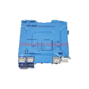
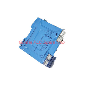

MTL5099 MTL Dummy Wiring Module | MTL5000 Series Earthing Solution
Manufacturer: MTL
Product No.: MTL5099
Condition: En stock
Product Type: Dummy Wiring Module
Product Origin: EN
Payment: T/T, Western Union
Weight: 300g
Shipping port: Xiamen
Warranty: 12 months
Tiempo estimado de entrega: 12-26 días (Internacional), 3-6 días (Estados Unidos).
Devolución dentro de los 30 días siguientes a la compra. Los aranceles e impuestos no son reembolsables.
Pago Seguro Garantizado
MTL5099 Dummy Isolator | Cable Termination and Earthing Module
The MTL5099 is a passive wiring module in the MTL5000 series. It provides termination and earthing facilities for unused cable cores from hazardous areas. Unlike an active isolator, the MTL5099 contains no electronic components. It organizes unused conductors at designated terminals and supports orderly field wiring in industrial control cabinets. Engineers can use this module alongside compatible MTL5000 interface units. Its defined terminal layout separates hazardous-area cores, earth, and safe-area cores for easier wiring management.
01 | Engineering Data at a Glance
| Manufacturer | MTL |
| Model | MTL5099 |
| Product Series | MTL5000 |
| Module Type | Passive dummy isolator / wiring termination module |
| Primary Function | Termination and earthing of unused cable cores |
| Electronic Components | None; passive wiring module |
| Installation Location | Safe area |
| Hazardous-Area Terminals | Terminals 1–5 |
| Earth Terminal | Terminal 6 |
| Safe-Area Terminals | Terminals 7–12 |
| Terminal Capacity | Up to 2.5 mm², according to the MTL5000 common specification |
| Mounting | 35 mm DIN rail |
| Operating Temperature | -20°C to +60°C, according to the MTL5000 common specification |
| Approximate Weight | 110 g |
| Isolation Reference | 250 V RMS between input, output, and power terminals; 1500 V RMS test between safe-area and hazardous-area terminals |
| Reference Datasheet Date | August 2008 |
Technical clarification: The isolation values above refer to the MTL5000 common specification. Confirm their precise applicability to the MTL5099 and the intended installation using the manufacturer's documentation.
02 | Terminal Architecture and Wiring Logic
The MTL5099 uses a clearly allocated 12-terminal arrangement. Each terminal group serves a defined wiring purpose.
| Terminal | Assignment | Engineering Purpose |
| 1 | Hazardous-area core | Termination of a designated field conductor |
| 2 | Hazardous-area core | Termination of a designated field conductor |
| 3 | Hazardous-area core | Termination of a designated field conductor |
| 4 | Hazardous-area core | Termination of a designated field conductor |
| 5 | Hazardous-area core | Termination of a designated field conductor |
| 6 | Earth | Designated earth connection |
| 7 | Safe-area core | Termination of a designated control-side conductor |
| 8 | Safe-area core | Termination of a designated control-side conductor |
| 9 | Safe-area core | Termination of a designated control-side conductor |
| 10 | Safe-area core | Termination of a designated control-side conductor |
| 11 | Safe-area core | Termination of a designated control-side conductor |
| 12 | Safe-area core | Termination of a designated control-side conductor |
- Terminals 1–5: Assigned to hazardous-area cable cores.
- Terminal 6: Reserved for the designated earth connection.
- Terminals 7–12: Assigned to safe-area cable cores.
Do not assume that every terminal pair forms an electrically isolated channel. Follow the official wiring diagram to establish the intended connections.
03 | How the MTL5099 Fits into an MTL5000 Installation
The MTL5099 supports cable management around compatible MTL5000 interface equipment. It provides designated termination points for conductors that no longer serve an active signal function. Typical engineering benefits include:
- Structured wiring: Keeps unused cores organized at defined terminals.
- Clear earthing arrangement: Provides a designated earth terminal for the specified wiring scheme.
- Panel consistency: Supports a more orderly layout around MTL5000 interface modules.
- Maintenance access: Helps technicians identify and inspect terminated conductors.
- Reduced wiring ambiguity: Separates hazardous-area and safe-area terminal groups by assignment.
Important distinction: The MTL5099 is not an active signal isolator, signal converter, relay amplifier, or surge protection device. It contains no electronics and does not independently diagnose field faults.
04 | Suitable Equipment and Application Scenarios
The MTL5099 is most relevant to installations that use compatible MTL5000-series interface equipment and require organized cable termination.
- Distributed control systems (DCS): Control cabinets with MTL5000 signal interface modules.
- Programmable logic controller (PLC) panels: Cabinets containing hazardous-area field wiring interfaces.
- Process instrumentation: Wiring systems for field switches, transmitters, and other instrument circuits, where the documented wiring scheme permits its use.
- Oil and gas facilities: Instrument marshalling cabinets that handle field cables from classified areas.
- Chemical plants: Control panels that require defined conductor termination and earthing arrangements.
- Plant modifications: Cabinets with unused cores after instrument removal, circuit changes, or equipment relocation.
- Maintenance and commissioning: Projects that require traceable conductor identification and controlled wiring changes.
Application suitability depends on the approved wiring design. The module does not replace required hazardous-area protection or certification.
05 | Installation and Inspection Workflow
- Verify the part: Confirm the full MTL5099 model number and the required terminal arrangement.
- Check the panel: Confirm the 35 mm DIN rail and available mounting space.
- Identify conductors: Trace each unused core to its source and destination before termination.
- Confirm terminal assignments: Use the manufacturer's wiring diagram to verify each connection.
- Check conductor size: Keep conductors within the documented terminal capacity of 2.5 mm².
- Verify earthing: Connect terminal 6 according to the approved installation design.
- Inspect terminations: Check conductor retention, insulation condition, and terminal identification.
- Update records: Revise the wiring schedule and cabinet drawings after completing the work.
Isolate circuits and follow the site's permit-to-work procedures before changing field wiring. Never terminate a conductor based only on its apparent position or wire color.
06 | Maintenance and Diagnostic Limitations
The MTL5099 has no electronic diagnostics or status indicators. Technicians must verify its condition through physical inspection and circuit checks.
| Observed Issue | Recommended Check |
| Unidentified unused conductor | Trace the cable against the approved wiring schedule. |
| Loose termination | Inspect conductor retention and follow the specified tightening procedure. |
| Unexpected earth continuity | Verify the intended earth path and inspect for unintended conductor contact. |
| Conflicting terminal records | Compare cabinet drawings with field labels and actual wiring. |
| Damaged insulation or terminal area | Isolate the circuit and assess the module and conductor condition. |
| Uncertain circuit separation | Check the manufacturer's diagram and perform approved continuity tests. |
Field example: During a cabinet modification, a removed proximity switch leaves several spare cable cores. A technician identifies each core, checks its circuit assignment, and terminates it using the approved MTL5099 wiring arrangement. The technician then checks earth continuity and updates the cabinet drawings. This process improves traceability and reduces uncertainty during future maintenance.
07 | Compatibility and Procurement Checks
Before selecting the MTL5099, confirm the following engineering details:
- The existing interface equipment belongs to a compatible MTL5000 installation.
- The required function is passive termination and earthing, not active signal conditioning.
- The terminal arrangement matches the intended cable and panel wiring design.
- The installation meets the specified temperature and mounting requirements.
- The conductor size complies with the documented terminal capacity.
- The proposed earthing arrangement matches the manufacturer's instructions and site standards.
- The completed installation meets applicable hazardous-area segregation and wiring requirements.
Do not select this module as a direct replacement for an active isolator. Confirm the required function and terminal diagram before ordering.
08 | Global PLC Spare HUB Review
From a panel engineering perspective, the MTL5099 addresses a specific but important task: managing unused conductors without introducing an active electronic function. In a plant upgrade, an instrument may be removed while its multicore cable remains in place. Leaving spare cores unidentified can complicate fault tracing and later modifications. A documented termination arrangement gives maintenance personnel a consistent reference point. The key engineering consideration is conductor identification. A passive module cannot determine whether a core remains connected to a field device or carries an unexpected voltage. Technicians must verify the circuit before termination. For replacement projects, we recommend matching the model number, terminal layout, mounting arrangement, and applicable MTL5000 documentation. This approach reduces ordering errors and supports more reliable cabinet maintenance.
09 | Packaging, Warranty, and Shipping
- Product: MTL5099 passive dummy isolator.
- Packaging: Protective packaging for transport and handling.
- Package contents: One MTL5099 module. Additional accessories or documents require order confirmation.
- Warranty: 12-month warranty, subject to the seller's applicable terms and conditions.
- Shipping options: FedEx, UPS, and DHL.
- Dispatch target: 24–48 hours after order confirmation, subject to stock availability and processing.
- Before ordering: Contact Global PLC Spare HUB to confirm availability, product details, and shipping arrangements.
10 | Frequently Asked Questions
Q1: Does the MTL5099 need an external power supply?
No. The MTL5099 is a passive wiring module. It contains no electronics and requires no operating power for its termination function.
Q2: Can the MTL5099 replace a spare active isolator in a control cabinet?
Not when the circuit requires signal conditioning, electrical isolation, or active monitoring. Use this module only when the approved design calls for its passive termination and earthing function.
Q3: What should a technician verify before connecting an unused core to the module?
Identify the conductor at both ends and confirm its circuit assignment. Follow site isolation procedures and verify the absence of hazardous voltage where required. Check the wiring diagram before connecting it to a designated terminal.
Q4: Does the MTL5099 provide continuity monitoring or an alarm for loose wiring?
No. The module has no electronic monitoring or alarm output. Technicians must use approved inspection and test procedures to verify wiring continuity and termination quality.
Q5: Which details help confirm the correct module for a cabinet modification?
Provide the complete model number, existing MTL5000 equipment references, terminal diagram, conductor size, mounting arrangement, and intended application. These details help the supplier verify functional suitability before shipment.
Request a Quote from Global PLC Spare HUB
Looking for the MTL5099 for a control cabinet upgrade or spare-parts inventory? Contact Global PLC Spare HUB for a quotation, availability confirmation, 12-month warranty terms, and shipping options through FedEx, UPS, or DHL.

Tags
P: ¿Son estas piezas 100% originales y nuevas?
R: Sí. Cada componente está garantizado como 100% original, completamente nuevo y sellado de fábrica. También ofrecemos una garantía integral de 12 meses para su tranquilidad.
P: ¿Qué tan rápido es el envío a mi país?
R: Para artículos en stock, ofrecemos envío el mismo día. El envío exprés internacional (DHL/FedEx/UPS) generalmente entrega en un plazo de 3 a 5 días hábiles en todo el mundo.
P: ¿Puedo obtener una cotización formal con los costos de envío?
R: Absolutamente. Nuestro equipo de ventas está listo para proporcionar una factura proforma (PI) detallada que incluya las tarifas de envío más competitivas para su ubicación.
P: ¿Ofrecen descuentos por pedidos al por mayor?
R: Ofrecemos precios basados en el volumen para proyectos grandes o pedidos de varios artículos. Póngase en contacto con nosotros para obtener nuestra Garantía de Mejor Precio.
Garantía Integral de 12 Meses
Cada pieza suministrada por Global PLC Spare Hub está cubierta por una garantía de 12 meses a partir de la fecha de la factura.
- Cobertura: Defectos funcionales y fallos de hardware bajo condiciones normales de funcionamiento.
- Compromiso: Ofrecemos reparación, reemplazo o un reembolso completo inmediato para cualquier componente defectuoso verificado, para minimizar su tiempo de ininactividad operativa.
Política de Devoluciones y Cambios
Ofrecemos una política de devolución de 30 días para asegurar que reciba la pieza exacta que su sistema requiere.
- Elegibilidad: Se aceptan devoluciones de artículos sin instalar en su embalaje original sellado de fábrica.
- Proceso de RMA: Póngase en contacto con nuestro equipo de soporte para obtener un número de Autorización de Devolución de Mercancía (RMA) antes del envío.
- Procesamiento Rápido: Los reembolsos o cambios se procesan dentro de 3 a 5 días hábiles después de que el artículo devuelto pasa nuestra inspección técnica.
¿Necesita Asistencia Técnica? ¿No está seguro de si esta pieza es compatible con su sistema? [Consulte a nuestros Ingenieros] antes de comprar para asegurar una compatibilidad del 100%.
La gente también compró


