


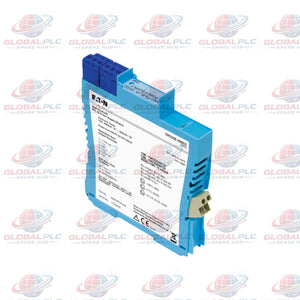

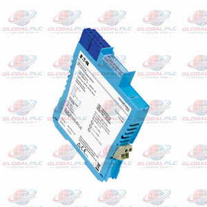
MTL MTL4581 Thermocouple Millivolt Signal Isolator
Manufacturer: MTL
Product No.: MTL4581
Condition: In stock
Product Type: Signal Conditioner
Product Origin: EN
Payment: T/T, Western Union
Weight: 200g
Shipping port: Xiamen
Warranty: 12 months
Estimate delivery times: 12-26 days (International), 3-6 days (United States).
Return within 30 days of purchase. Duties & taxes are non-refundable.
Guaranteed Safe Checkout
Product Overview
The MTL4581 is a single-channel millivolt signal isolator from MTL Instruments. It receives low-level DC signals from hazardous areas and transfers isolated signals to safe-area instruments.
The MTL4581 supports thermocouple applications with external cold-junction compensation. It also accepts other DC millivolt sources within its specified measurement range.
Two configuration switches control the thermocouple burnout response:
- Safety Drive Selection: Enables or disables the safety-drive function during thermocouple burnout or cable breakage.
- Fault Direction Selection: Configures upscale or downscale output operation according to receiving instrument requirements.
This configuration provides flexible fault handling for industrial temperature monitoring and process instrumentation.
Technical Specifications
| Manufacturer | MTL Instruments |
| Model | MTL4581 |
| Product Type | Single-Channel Millivolt Signal Isolator |
| Number of Channels | 1 |
| Signal Source | Any DC millivolt source |
| Input Signal Range | 0 to ±50 mV |
| Output Signal Range | 0 to ±50 mV |
| Overrange Capability | Up to ±55 mV |
| Maximum Lead Resistance | 600 Ω |
| Output Resistance | 60 Ω nominal |
| Linearity and Repeatability | <0.05% of reading or ±5 μV, whichever is greater |
| Transfer Accuracy Reference | 20°C |
| Temperature Drift | <2 μV/°C maximum |
| Response Time | Within 10% of final value in 150 μs |
| Frequency Response | DC to 4 kHz nominal |
| Cold-Junction Compensation | External |
| Thermocouple Burnout Response | Configurable safety drive |
| Fault Direction | Upscale or downscale |
| Power Supply | 20–35 V DC |
| Maximum Current Consumption | 30 mA |
| Power Dissipation at 24 V | 0.7 W typical |
| Power Dissipation at 35 V | 0.91 W |
| LED Indicator | Green power indicator |
| Hazardous-Area Application | Zone 0, IIC, T4–T6, subject to suitable certification |
| North American Application | Division 1, Group A, subject to applicable approval |
Core Technical Performance
1. Millivolt Signal Measurement
- Accepts DC millivolt signals from 0 to ±50 mV.
- Provides overrange capability up to ±55 mV.
- Supports various DC voltage sources, including thermocouples.
- Allows maximum field lead resistance of 600 Ω.
2. Signal Accuracy and Stability
- Linearity and repeatability remain below 0.05% of reading or ±5 μV.
- Maximum temperature drift remains below 2 μV/°C.
- The specified transfer performance references 20°C.
3. Dynamic Signal Response
- Nominal frequency response extends from DC to 4 kHz.
- Response settles within 10% of final value in 150 μs.
- Nominal output resistance is 60 Ω.
4. Thermocouple Fault Handling
- Two switches configure the thermocouple burnout response.
- Users can enable or disable the safety-drive function.
- The second switch selects upscale or downscale operation.
- This arrangement supports different receiving instrument requirements.
5. Power Requirements
- Accepts a 20–35 V DC supply.
- Maximum current consumption reaches 30 mA.
- Typical power dissipation is 0.7 W at 24 V.
- Power dissipation reaches 0.91 W at 35 V.
- A green LED indicates power availability.
Installation Guide
1. Verify Installation Conditions
- Check the hazardous-area classification before installation.
- Confirm applicable Zone or Division requirements.
- Review the approved intrinsic safety documentation.
2. Connect the Power Supply
- Provide a 20–35 V DC supply.
- Verify supply polarity and terminal assignments.
- Check the available power budget before energizing.
3. Connect the Millivolt Input
- Connect the field millivolt source to the designated input terminals.
- Keep field lead resistance within the 600 Ω limit.
- Use suitable instrumentation cable and shielding where required.
- Follow the manufacturer's approved wiring diagram.
4. Connect the Receiving Instrument
- Connect the isolated output to the safe-area instrument.
- Verify its millivolt input range.
- Check compatibility with the nominal 60 Ω output resistance.
5. Configure Fault Response
- Set the safety-drive switch according to application requirements.
- Select the appropriate upscale or downscale response.
- Verify the receiving instrument's response during simulated fault conditions.
Commissioning and Maintenance
Commissioning Checklist
- Measure the DC supply voltage before testing.
- Confirm the green power LED illuminates.
- Apply a calibrated millivolt input.
- Compare receiving instrument readings against the input source.
- Test signal response across the intended measurement range.
- Verify upscale or downscale fault behavior.
- Confirm external cold-junction compensation operates correctly.
Routine Maintenance Recommendations
- Inspect terminals for loose connections and corrosion.
- Check field cable resistance during scheduled maintenance.
- Compare signal readings against a calibrated reference source.
- Investigate drift beyond the specified temperature coefficient.
- Check the power indicator during routine inspections.
- Retest burnout response after field wiring modifications.
Intrinsic Safety and Certification Information
The MTL4581 provides the following intrinsic safety description for terminals 1–2.
| Parameter | Specification |
| Terminal Pair | 1–2 |
| Apparatus Classification | Non-energy-storing apparatus |
| Maximum Voltage | ≤1.5 V |
| Maximum Current | ≤0.1 A |
| Maximum Power | ≤25 mW |
| IS Loop Connection | May connect without further certification to an IS loop with open-circuit voltage below 28 V |
Hazardous-Area Application Conditions
- Zone 0, IIC, T4–T6 applications require suitable certification.
- Division 1, Group A applications require applicable approval.
- Verify complete loop parameters before installation.
- Check product markings and official approval documents.
Note: The supplied technical information does not identify a specific certificate number. Confirm the exact approval status against the product label and manufacturer's documentation.
Packaging and Delivery
- MTL4581 millivolt signal isolator module.
- Protective packaging for transportation.
- Product identification and model verification.
Please confirm the exact package contents and accessories with our sales team before ordering. Additional accessories and documentation depend on the supplied configuration.
Global PLC Spare HUB's Insight
The MTL4581 addresses a specific instrumentation requirement: isolated transmission of low-level millivolt signals from hazardous areas.
Its 4 kHz nominal bandwidth supports dynamic signal transmission. The 150 μs response time enables rapid output tracking. Specified linearity and repeatability support consistent measurement performance.
Engineers should pay particular attention to external cold-junction compensation. Incorrect compensation can introduce significant temperature measurement errors.
The configurable burnout response also requires careful commissioning. An incorrect upscale or downscale setting can produce unexpected fault indications.
Before replacing an existing isolator, compare the terminal arrangement, supply voltage, signal range, intrinsic safety parameters, and fault-response settings. Matching the model number alone does not guarantee electrical compatibility.
Frequently Asked Questions (FAQ)
Q1: What is the primary function of the MTL4581?
The MTL4581 isolates low-level DC millivolt signals from hazardous areas. It transfers these signals to safe-area receiving instruments.
Q2: Can the MTL4581 connect directly to a thermocouple?
Yes. It accepts thermocouple millivolt signals. However, the application requires external cold-junction compensation.
Q3: What happens when a thermocouple cable breaks?
The module provides configurable safety-drive behavior. Two switches enable or disable this function and select upscale or downscale operation.
Q4: How should engineers select upscale or downscale operation?
Check the receiving instrument's fault-handling requirements first. Select the direction that produces the required fault indication. Verify the complete control system response during commissioning.
Q5: Can the MTL4581 replace another millivolt signal isolator?
Potentially. Compare signal ranges, accuracy, supply voltage, terminal assignments, and intrinsic safety parameters. Verify fault-response settings before replacement.
Q6: Does the MTL4581 provide integrated cold-junction compensation?
No. It supports thermocouple applications with external cold-junction compensation. The external compensation device must match the thermocouple configuration.
Q7: What should buyers verify before ordering the MTL4581?
Confirm the complete model number and application requirements. Check input range, output range, power supply, fault response, and hazardous-area classification. Request wiring diagrams and certification evidence when necessary.
Q8: What causes inaccurate readings when using the MTL4581?
Common causes include incorrect cold-junction compensation, excessive lead resistance, poor terminal connections, and unsuitable fault settings. Compare input and output signals against a calibrated millivolt source.
Q9: How can maintenance teams verify signal accuracy?
Apply calibrated millivolt signals at several measurement points. Compare receiving instrument readings against source values. Check temperature drift and repeatability against published specifications.
Q10: What information should buyers provide when requesting a quotation?
Provide the MTL4581 model number, required quantity, application details, and delivery destination. Include hazardous-area requirements and certification needs. This information helps our team verify the correct configuration.
Send us your model number and required quantity to receive a quotation.

Tags
Q: Are these parts 100% original and new?
A: Yes. Every component is guaranteed to be 100% original, brand-new, and factory-sealed. We also provide a 12-month comprehensive warranty for your peace of mind.
Q: How fast is the shipping to my country?
A: For in-stock items, we offer same-day dispatch. International express shipping (DHL/FedEx/UPS) typically delivers within 3–5 business days worldwide.
Q: Can I get a formal quotation with shipping costs?
A: Absolutely. Our sales team is ready to provide a detailed Proforma Invoice (PI) including the most competitive shipping rates for your location.
Q: Do you offer discounts for bulk orders?
A: We provide volume-based pricing for large projects or multiple-item orders. Please contact us to get our Best Price Guarantee.
12-Month Comprehensive Warranty
Every part supplied by Global PLC Spare Hub is covered by a 12-month warranty from the date of invoice.
- Coverage: Functional defects and hardware failures under normal operating conditions.
- Commitment: We provide immediate repair, replacement, or a full refund for any verified defective components to minimize your operational downtime.
Returns & Exchange Policy
We offer a 30-day return policy to ensure you receive the exact part your system requires.
- Eligibility: Returns are accepted for uninstalled items in their original, factory-sealed packaging.
- RMA Process: Please contact our support team to obtain a Return Merchandise Authorization (RMA) number before shipping.
- Fast Processing: Refunds or exchanges are processed within 3–5 business days after the returned item passes our technical inspection.
Need Technical Assistance?Not sure if this part is compatible with your system? [Consult our Engineers] before purchasing to ensure 100% compatibility.
People Also Bought


