


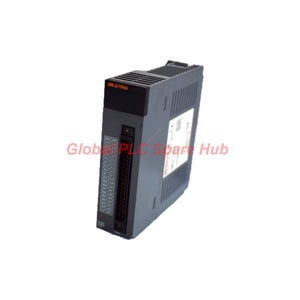
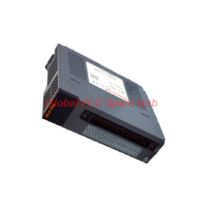
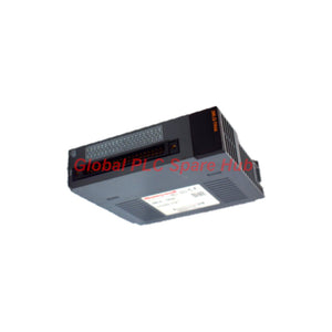
2MLQ-TR4A Honeywell MasterLogic-200 32-Point Transistor Output Module
Manufacturer: Honeywell
Product No.: 2MLQ-TR4A
Condition: In stock
Product Type: Transistor Output Module
Product Origin: USA
Payment: T/T, Western Union
Weight: 500g
Shipping port: Xiamen
Warranty: 12 months
Estimate delivery times: 12-26 days (International), 3-6 days (United States).
Return within 30 days of purchase. Duties & taxes are non-refundable.
Guaranteed Safe Checkout
Output Module Engineering Profile
2MLQ-TR4A is a 32-point digital output module from Honeywell MasterLogic-200 Series. It provides isolated DC switching outputs for industrial automation applications.
The module uses photocoupler isolation to separate output control circuits from internal logic circuits. Each output point supports a maximum load current of 0.1 A. The common terminal supports a maximum combined current of 2 A.
Its fast switching characteristics support applications requiring short output response times. Both ON and OFF transitions complete within 1 ms under specified resistive load conditions.
A 40-pin connector provides the external electrical interface. The module also incorporates Zener diode surge absorption for output circuit protection.
01 | Electrical Architecture & Output Configuration
- 32 independent output points: Provides multiple switching channels within one module.
- Photocoupler isolation: Separates control and output circuits electrically.
- 32 points / 1 COM: All output points share one common connection.
- DC switching: Supports nominal 12 VDC and 24 VDC load systems.
- Fast response: ON and OFF response times are both 1 ms or less.
- Zener diode protection: Provides surge absorption for output circuits.
02 | Complete Technical Data
| Technical Item | Specification |
| Manufacturer | Honeywell |
| Model | 2MLQ-TR4A |
| Product Series | MasterLogic-200 |
| Product Type | Digital Output Module |
| Output Points | 32 points |
| Isolation Method | Photocoupler isolation |
| Rated Load Voltage | 12 / 24 VDC |
| Load Voltage Range | 10.2–26.4 VDC |
| Maximum Load Current | 0.1 A per point |
| Maximum Common Current | 2 A per COM |
| Common Configuration | 32 points / 1 COM |
| OFF-State Leakage Current | 0.1 mA or less |
| Maximum Inrush Current | 0.7 A for 10 ms or less |
| ON-State Voltage Drop | 0.2 VDC or less |
| Surge Absorber | Zener diode |
| ON Response Time | 1 ms or less |
| OFF Response Time | 1 ms or less |
| Response Test Condition | Rated resistive load |
| Current Consumption | 130 mA with all points ON |
| External Voltage | 12 / 24 VDC ±10% |
| Permitted Ripple Voltage | 4 Vp-p or less |
| Power Supply Current | 10 mA or less at 24 VDC connection |
| Operation Indicator | LED indication for ON status |
| External Connection | 40-pin connector |
| Recommended Cable Size | 0.3 mm² |
| Weight | 0.1 kg |
03 | Output Loading & Switching Performance
Individual Channel Capacity
- Maximum continuous load current: 100 mA per point.
- Maximum common current: 2 A per COM.
- Maximum inrush current: 700 mA for up to 10 ms.
- OFF-state leakage current: Maximum 0.1 mA.
Engineers must evaluate both individual channel loading and total common current. The 2 A common limit remains applicable when multiple points operate simultaneously.
Switching Characteristics
- OFF-to-ON response: 1 ms maximum.
- ON-to-OFF response: 1 ms maximum.
- Maximum ON-state voltage drop: 0.2 VDC.
- Specified response conditions: Rated resistive load.
These characteristics support fast control signals and frequent switching applications. Actual field performance also depends on load characteristics and external wiring.
04 | Electrical Protection & Power Requirements
Isolation Architecture
Photocoupler isolation provides electrical separation between control and output circuits. This arrangement helps reduce the effects of electrical disturbances on control-side electronics.
Surge Absorption
The output circuit uses a Zener diode surge absorber. The supplied specification references IEC 61006-6-2. Confirm the exact standard designation against the applicable manufacturer document.
External Power Conditions
- Nominal external voltage: 12 VDC or 24 VDC.
- Permitted voltage tolerance: ±10%.
- Maximum specified ripple: 4 Vp-p.
- Internal current consumption: 130 mA with all outputs ON.
- External connection power supply current: 10 mA or less at 24 VDC.
Check the external load supply separately from the PLC module supply. Confirm voltage stability before connecting field loads.
05 | Installation & Wiring Procedure
Step 1: Verify the Hardware Configuration
- Confirm the module reference before installation.
- Check compatibility with the installed MasterLogic-200 PLC configuration.
- Verify the required output voltage and load characteristics.
Step 2: Prepare the Connector
- Use the specified 40-pin external connection.
- Prepare suitable wiring with a recommended cross-section of 0.3 mm².
- Check connector orientation and terminal assignments against the wiring diagram.
Step 3: Check the Load Circuit
- Confirm that each output stays within the 0.1 A limit.
- Keep the combined current within the 2 A common limit.
- Verify the external supply polarity and voltage.
- Check inductive load suppression requirements before connection.
Step 4: Perform Initial Power-Up
- Inspect wiring before applying power.
- Check the external supply voltage under load.
- Observe the module's operation indicators.
- Test each output point individually.
06 | Commissioning & Field Diagnostics
Output Point Does Not Switch
- Check PLC logic and output command status.
- Measure the external supply voltage.
- Inspect the 40-pin connector and cable continuity.
- Measure the load resistance and operating current.
Unexpected Load Operation
- Check the OFF-state leakage current.
- Inspect field wiring for unintended voltage paths.
- Verify the load's minimum operating current.
- Check for external wiring faults.
Output Voltage Drop
- Measure the voltage directly across the output circuit.
- Compare the result with the 0.2 VDC maximum specification.
- Check terminal contact resistance and cable connections.
- Verify that the channel current remains within limits.
Intermittent Switching
- Check external supply ripple and voltage stability.
- Inspect connector seating and cable condition.
- Review common terminal loading.
- Investigate electrical interference from nearby switching equipment.
07 | System Integration & Application Scope
The MasterLogic-200 2MLQ-TR4A provides DC digital switching for PLC-controlled equipment.
Typical application areas include:
- Solenoid valve control in process automation systems.
- Relay interface circuits in industrial control cabinets.
- Indicator lamps and panel signaling circuits.
- Low-current actuator control.
- Conveyor and packaging machine control.
- Auxiliary switching circuits in manufacturing equipment.
- Distributed digital output applications.
Compatibility Verification
Confirm the PLC CPU, rack configuration, firmware, and module installation position before ordering. Check the output wiring diagram and connector pin assignment.
Do not assume compatibility with other Honeywell PLC families. Verify the exact MasterLogic-200 hardware configuration first.
08 | Engineering Notes: Selection & Maintenance
Load Selection
Calculate the total current for all simultaneously energized output points. Never exceed the 2 A common terminal limit.
Inductive Loads
Solenoids and relay coils can generate transient voltages during switching. Verify the load suppression arrangement and polarity requirements before installation.
Power Supply Selection
Consider the external supply voltage, ripple, and total load demand. Allow sufficient supply capacity for simultaneous switching conditions.
Preventive Maintenance
- Inspect connector contacts during scheduled maintenance.
- Check cable insulation and terminal connections.
- Review output current distribution across the common terminal.
- Test switching response when abnormal operation occurs.
- Record output status and field load measurements.
09 | Global PLC Spare HUB's Engineering Insight
The key selection consideration for this module is its shared common-current limitation. Each channel supports 100 mA, but the common terminal supports 2 A total.
This distinction matters when engineers operate many solenoid valves or indicator circuits simultaneously. A design based only on individual channel ratings may overload the common connection.
The 1 ms switching specification also requires careful interpretation. It describes module response under rated resistive load conditions. Inductive loads may introduce additional electrical transients.
During commissioning, test output points under their actual operating loads. Measure supply stability and common-terminal current before final acceptance.
10 | Professional FAQ
Q1: Can all 32 output points operate simultaneously?
Yes, simultaneous operation is subject to electrical loading limits. The total current must remain within 2 A per common terminal. Calculate the combined load before assigning all output points.
Q2: Why does an output LED turn ON while the connected device remains inactive?
The control command and the physical load circuit require separate verification. Check the external supply, connector pinout, common wiring, and load continuity. An illuminated indicator alone does not confirm current flow through the field device.
Q3: Can the module directly drive a large contactor coil?
Check the coil's steady-state and inrush current first. Both must satisfy the applicable output ratings. Use an appropriately rated interposing relay when the load exceeds the module's limits.
Q4: What should engineers consider when connecting multiple inductive loads?
Evaluate simultaneous switching, transient voltage, and common-terminal loading. Check whether each field device requires additional suppression. Do not assume the built-in Zener protection covers every external load condition.
Q5: How can engineers identify a module-related fault without immediately replacing the hardware?
Compare PLC output commands with LED indications and measured terminal voltages. Test the external supply and cable continuity. Disconnect the field load under safe isolation procedures and perform a controlled output test. This approach helps separate PLC logic, wiring, load, and module faults.
11 | Supply, Packaging & Warranty
- Supplier: Ubest Automation Limited.
- Product: Honeywell 2MLQ-TR4A digital output module.
- Quantity: 1 module per standard order unit.
- Packaging: Protective export packaging.
- Product condition: New and original, subject to order confirmation.
- Inspection: Model and external condition checked before shipment.
- Warranty: 12 months.
- Shipping: FedEx, UPS, and DHL international delivery.
- Technical assistance: Model identification and compatibility support.
Request a Quotation
Need the Honeywell 2MLQ-TR4A MasterLogic-200 32-point output module for your control system?
Contact Ubest Automation for current pricing, availability, and delivery information.
Email: sales@ubestplc.com
Website: ubestplc.com
Send your model number and quantity requirements for a prompt quotation.
Tags
Q: Are these parts 100% original and new?
A: Yes. Every component is guaranteed to be 100% original, brand-new, and factory-sealed. We also provide a 12-month comprehensive warranty for your peace of mind.
Q: How fast is the shipping to my country?
A: For in-stock items, we offer same-day dispatch. International express shipping (DHL/FedEx/UPS) typically delivers within 3–5 business days worldwide.
Q: Can I get a formal quotation with shipping costs?
A: Absolutely. Our sales team is ready to provide a detailed Proforma Invoice (PI) including the most competitive shipping rates for your location.
Q: Do you offer discounts for bulk orders?
A: We provide volume-based pricing for large projects or multiple-item orders. Please contact us to get our Best Price Guarantee.
12-Month Comprehensive Warranty
Every part supplied by Global PLC Spare Hub is covered by a 12-month warranty from the date of invoice.
- Coverage: Functional defects and hardware failures under normal operating conditions.
- Commitment: We provide immediate repair, replacement, or a full refund for any verified defective components to minimize your operational downtime.
Returns & Exchange Policy
We offer a 30-day return policy to ensure you receive the exact part your system requires.
- Eligibility: Returns are accepted for uninstalled items in their original, factory-sealed packaging.
- RMA Process: Please contact our support team to obtain a Return Merchandise Authorization (RMA) number before shipping.
- Fast Processing: Refunds or exchanges are processed within 3–5 business days after the returned item passes our technical inspection.
Need Technical Assistance?Not sure if this part is compatible with your system? [Consult our Engineers] before purchasing to ensure 100% compatibility.
People Also Bought


