


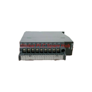
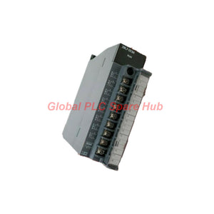
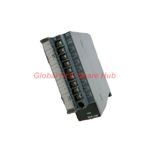
2MLF-DC8A Honeywell PLC MasterLogic-200 Current Output Module
Manufacturer: Honeywell
Product No.: 2MLF-DC8A
Condition: In stock
Product Type: Current Output Module
Product Origin: USA
Payment: T/T, Western Union
Weight: 500g
Shipping port: Xiamen
Warranty: 12 months
Estimate delivery times: 12-26 days (International), 3-6 days (United States).
Return within 30 days of purchase. Duties & taxes are non-refundable.
Guaranteed Safe Checkout
01 | Product Identity – Analog Output Architecture
Honeywell 2MLF-DC8A is an eight-channel analog current output module for the MasterLogic-200 PLC Series.
The module converts PLC-generated control values into industrial current signals. It supports two selectable output ranges: 4–20 mA DC and 0–20 mA DC.
Each channel supports individual output range selection through the applicable PLC program or configuration parameters. This flexibility allows engineers to configure different current signal requirements within one module.
The module supports external loads with resistance up to 550 Ω. It provides an interface between the PLC control logic and field devices requiring analog current commands.
Primary Engineering Applications
- Control valve position command signals.
- Variable frequency drive speed references.
- Industrial actuator control.
- Process flow and pressure control loops.
- Analog command distribution to field equipment.
02 | Hardware Identification
| Parameter | Technical Information |
|---|---|
| Manufacturer | Honeywell |
| Model | 2MLF-DC8A |
| Product Series | MasterLogic-200 |
| Product Category | Analog Output Module |
| Output Type | Analog Current Output |
| Number of Channels | 8 |
| Output Signal | DC 4–20 mA / DC 0–20 mA |
| Maximum Load Resistance | 550 Ω |
| Output Range Selection | Program or channel-specific parameters |
| Channel Configuration | Individually selectable output ranges |
03 | Current Output Engineering – Signal Characteristics
The 2MLF-DC8A provides eight current output channels for industrial control applications. Each channel supports the selected current range.
| Output Parameter | Specification |
|---|---|
| Channel Quantity | 8 |
| Current Range 1 | 4–20 mA DC |
| Current Range 2 | 0–20 mA DC |
| Range Configuration | Program or channel-specific parameters |
| Maximum Load Resistance | 550 Ω or less |
| Output Signal Type | Analog current |
4–20 mA Operating Mode
The 4–20 mA range supports common industrial live-zero signal transmission. The 4 mA lower limit represents the configured zero-scale command.
The 20 mA upper limit represents the configured full-scale command. The live-zero arrangement helps distinguish a valid zero-scale command from certain wiring faults.
0–20 mA Operating Mode
The 0–20 mA range provides a direct current command starting at zero. It suits control systems that require a zero-based output scale.
Engineers should select the output mode according to the receiving instrument. Incorrect range selection can produce scaling errors in the controlled equipment.
04 | Load Compatibility & Output Circuit Design
The specified maximum load resistance is 550 Ω. The complete output loop must remain within this limit.
When evaluating the current loop, include the resistance of the receiving device, signal cable, and any series-connected components.
Load Calculation Reference
| Design Item | Engineering Consideration |
|---|---|
| Output Load | 550 Ω maximum |
| Receiving Device | Verify current input compatibility |
| Signal Cable | Include cable loop resistance |
| Series Components | Include additional circuit resistance |
| Output Scaling | Match PLC engineering units to field device range |
Example: A receiving instrument with 250 Ω input resistance leaves up to 300 Ω for the remaining output loop components.
This example assumes a 550 Ω maximum total load. Confirm actual circuit requirements against the module hardware manual.
05 | PLC Configuration & Channel Assignment
The module supports output range selection through the applicable PLC program or channel-specific parameters.
Recommended Configuration Workflow
- Install the module in a compatible MasterLogic-200 system.
- Confirm hardware recognition in the PLC configuration.
- Identify all eight output channel assignments.
- Select 4–20 mA or 0–20 mA for each applicable channel.
- Configure engineering scaling in the PLC application.
- Match each output range with its receiving instrument.
- Verify output commands using suitable measurement equipment.
- Document the final channel configuration.
Engineering Note: Do not assume that all channels share the same output range. Verify the individual channel parameters before commissioning.
06 | Field Integration & Application Examples
The eight current outputs support multiple analog control loops within one PLC system.
| Application | Output Function | Engineering Consideration |
|---|---|---|
| Control Valve | Valve position command | Match the actuator input range. |
| Variable Frequency Drive | Speed reference | Verify the drive's current input configuration. |
| Pressure Controller | Setpoint transmission | Confirm scaling and signal direction. |
| Flow Control System | Flow command output | Match the receiving controller range. |
| Process Actuator | Analog operating command | Check load resistance and loop wiring. |
07 | Installation & Commissioning Guidelines
Hardware Installation
- Confirm compatibility with the MasterLogic-200 PLC architecture.
- Inspect the module and installation position.
- Follow the manufacturer's rack installation procedure.
- Verify terminal assignments before connecting field wiring.
- Check the receiving equipment's current input requirements.
Electrical Commissioning
- Verify the PLC hardware configuration.
- Confirm the selected output range for each channel.
- Check the field wiring and receiving circuit.
- Measure the output current with suitable test equipment.
- Apply representative low, intermediate, and high output commands.
- Compare measured current with the configured engineering scale.
- Verify the response of connected actuators or controllers.
Commissioning Recommendation
Test each output channel independently before enabling automatic control. This procedure helps identify channel assignment errors and incorrect current range settings.
08 | Troubleshooting & Maintenance
| Observed Symptom | Possible Cause | Recommended Check |
|---|---|---|
| Output current is incorrect | Incorrect range selection | Check the channel configuration. |
| Output does not reach full scale | Excessive loop resistance | Measure total circuit resistance. |
| Receiving device shows incorrect values | Scaling mismatch | Compare PLC scaling with receiver settings. |
| One channel behaves differently | Channel parameter mismatch | Review individual channel configuration. |
| Field device does not respond | Wiring or receiving input problem | Inspect loop continuity and device settings. |
Preventive Maintenance
- Inspect output wiring and terminal connections.
- Check current loop resistance during scheduled maintenance.
- Compare measured output values with PLC commands.
- Review channel-specific configuration parameters.
- Document changes to output scaling and field devices.
09 | System Compatibility & Selection Considerations
The Honeywell 2MLF-DC8A is designed for the MasterLogic-200 PLC platform. Confirm the controller and rack configuration before selecting this module.
Selection Checklist
- Confirm the required eight-channel output capacity.
- Verify the 4–20 mA or 0–20 mA signal requirement.
- Check each receiving device's current input specification.
- Calculate the complete loop resistance.
- Confirm individual channel configuration requirements.
- Verify compatibility with the existing PLC hardware and software.
Do not assume direct compatibility with analog output modules from other Honeywell product families. Compare hardware interfaces, channel mapping, configuration parameters, and electrical characteristics.
10 | Technical FAQ – Engineering & Procurement
Q1: Can the module control several different types of field equipment simultaneously?
Yes, its eight channels can serve different analog control loops. Engineers should configure each channel according to its receiving device. Verify signal ranges and load resistance for every connected circuit.
Q2: How should engineers select between 4–20 mA and 0–20 mA?
Choose 4–20 mA when the receiving instrument uses a live-zero measurement convention. Select 0–20 mA when the application requires a zero-based current scale. Both devices must use matching configurations.
Q3: What happens if the receiving circuit exceeds the 550 Ω load limit?
The output may fail to achieve the commanded current. Excessive resistance can affect control accuracy and signal stability. Review cable length, receiver impedance, and series-connected components before installation.
Q4: How can engineers identify a channel configuration error during startup?
Compare the programmed current range with the receiving device configuration. Apply a known output command and measure the actual loop current. Repeat the test across all eight channels to identify inconsistent settings.
Q5: What information should procurement teams confirm before ordering this module?
Confirm the complete part number, MasterLogic-200 platform, eight-channel requirement, and required current ranges. Also verify the maximum load resistance and existing PLC configuration. Request technical documentation when planning replacement or system expansion.
11 | Product Identification & Procurement Support
Honeywell 2MLF-DC8A provides eight configurable analog current outputs for MasterLogic-200 industrial control systems.
Its selectable 4–20 mA and 0–20 mA ranges support flexible integration with process instruments and field actuators. The 550 Ω load limit provides a clear reference for current loop engineering.
Contact our sales team for 2MLF-DC8A quotations, product availability, technical specifications, and MasterLogic-200 compatibility assistance.
Tags
Q: Are these parts 100% original and new?
A: Yes. Every component is guaranteed to be 100% original, brand-new, and factory-sealed. We also provide a 12-month comprehensive warranty for your peace of mind.
Q: How fast is the shipping to my country?
A: For in-stock items, we offer same-day dispatch. International express shipping (DHL/FedEx/UPS) typically delivers within 3–5 business days worldwide.
Q: Can I get a formal quotation with shipping costs?
A: Absolutely. Our sales team is ready to provide a detailed Proforma Invoice (PI) including the most competitive shipping rates for your location.
Q: Do you offer discounts for bulk orders?
A: We provide volume-based pricing for large projects or multiple-item orders. Please contact us to get our Best Price Guarantee.
12-Month Comprehensive Warranty
Every part supplied by Global PLC Spare Hub is covered by a 12-month warranty from the date of invoice.
- Coverage: Functional defects and hardware failures under normal operating conditions.
- Commitment: We provide immediate repair, replacement, or a full refund for any verified defective components to minimize your operational downtime.
Returns & Exchange Policy
We offer a 30-day return policy to ensure you receive the exact part your system requires.
- Eligibility: Returns are accepted for uninstalled items in their original, factory-sealed packaging.
- RMA Process: Please contact our support team to obtain a Return Merchandise Authorization (RMA) number before shipping.
- Fast Processing: Refunds or exchanges are processed within 3–5 business days after the returned item passes our technical inspection.
Need Technical Assistance?Not sure if this part is compatible with your system? [Consult our Engineers] before purchasing to ensure 100% compatibility.
People Also Bought


