


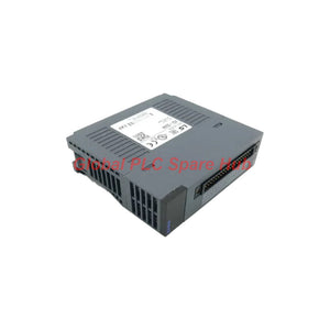
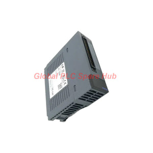
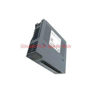
2MLI-D24A Honeywell 24V DC Input Module | Reliable 32-Point
Manufacturer: Honeywell
Product No.: 2MLI-D24A
Condition: In stock
Product Type: DC Input Module
Product Origin: USA
Payment: T/T, Western Union
Weight: 500g
Shipping port: Xiamen
Warranty: 12 months
Estimate delivery times: 12-26 days (International), 3-6 days (United States).
Return within 30 days of purchase. Duties & taxes are non-refundable.
Guaranteed Safe Checkout
2MLI-D24A | Honeywell 32-Point 24V DC Digital Input Module
The Honeywell 2MLI-D24A is a 32-point digital input module designed for 24 V DC field signal acquisition. It receives discrete signals from industrial switches, sensors, and control devices, then transfers their input states to the controller.
Each input channel uses photocoupler isolation. The module supports current source and current sink input configurations, allowing it to interface with different field wiring arrangements when connected according to the system wiring requirements.
Its CPU-configurable response time provides flexibility when handling signals with different switching characteristics. Engineers can select an appropriate input response setting to balance signal filtering and control responsiveness.
01 | Input Signal Interface – 32 Independent Input Points
The module provides 32 digital input points with a rated input voltage of 24 V DC. Each point detects field signal conditions according to the specified ON and OFF thresholds.
| Input Characteristic | Specification |
|---|---|
| Module type | Digital input module |
| Number of input points | 32 |
| Rated input voltage | 24 V DC |
| Rated input current | Approximately 4 mA |
| Input resistance | Approximately 5.6 kΩ |
| Input configuration | Current source / current sink |
| Isolation method | Photocoupler isolation |
| Common arrangement | 32 points / COM |
| Input derating | Yes |
The 32-point configuration allows multiple discrete field signals to share one module position. Typical signals include limit switches, auxiliary contacts, and digital status outputs from field equipment.
02 | Logic Thresholds – How the Module Recognizes ON and OFF States
Reliable digital input detection depends on the voltage and current delivered by the field circuit. The specified thresholds define the electrical conditions for recognizing valid input states.
| Logic Condition | Voltage Requirement | Current Requirement |
|---|---|---|
| ON | 19 V DC or higher | 3 mA or higher |
| OFF | 11 V DC or lower | 1.7 mA or lower |
Engineering consideration: The region between the specified ON and OFF thresholds should not be treated as a guaranteed logic state. If the field voltage fluctuates around this region, the controller may not receive a stable input condition.
During commissioning, measure the voltage at the module terminals under actual load conditions. Do not rely only on the nominal voltage printed on the field sensor.
03 | Response Time – CPU-Configurable Input Filtering
The 2MLI-D24A supports multiple input response settings. The CPU parameter determines the selected delay for both OFF-to-ON and ON-to-OFF transitions.
| Transition | Selectable Response Settings | Default |
|---|---|---|
| OFF → ON | 1 / 3 / 5 / 10 / 20 / 70 / 100 ms | 3 ms |
| ON → OFF | 1 / 3 / 5 / 10 / 20 / 70 / 100 ms | 3 ms |
The configurable response time helps engineers adapt input recognition to the field device and application. A shorter setting supports faster state detection. A longer setting can help reject brief signal changes caused by contact bounce or electrical interference.
Commissioning tip: Start with the default 3 ms setting when the application permits. If the input status changes repeatedly during contact switching, inspect the wiring and signal quality before increasing the response time. Excessive filtering can delay the detection of genuine machine events.
04 | Electrical Supply and Isolation Performance
The input circuit is designed for a nominal 24 V DC field supply. The operating voltage range and isolation ratings define important limits for panel design and field wiring.
| Electrical Parameter | Specification |
|---|---|
| Operating voltage range | 20.4–28.8 V DC |
| Permitted ripple rate | Less than 5% |
| Isolation method | Photocoupler |
| Isolation voltage | 560 V AC rms / 3 cycles, at 2,000 m altitude |
| Isolation resistance | 10 MΩ or higher by megger |
| Current consumption | 50 mA |
Photocoupler isolation provides electrical separation between the input signal circuitry and the internal logic side. The stated 560 V AC rms rating applies to the specified test condition; it should not be interpreted as a continuous operating voltage rating.
Keep the field supply within the specified 20.4–28.8 V DC range and maintain ripple below 5%. Poor supply quality can cause unstable input recognition, even when the field device itself operates correctly.
05 | Wiring and Connector Arrangement
The module uses a 40-point connector for external signal connection. Its common arrangement is specified as 32 points per COM.
- External connection: 40-point connector.
- Input common: 32 points / COM.
- Recommended cable size: 0.3 mm².
- Supported input wiring: Current source and current sink configurations.
- Input indication: LED turns ON when the corresponding input is active.
Before wiring, confirm the connector pin assignment and common terminal arrangement in the applicable Honeywell wiring documentation. Do not assume that all 32 input points can use independent commons.
For source and sink circuits, verify the field device's output topology and the module's terminal reference. Incorrect polarity or common wiring can prevent the input from reaching its valid ON threshold.
06 | Installation and Diagnostic Workflow
Use a structured verification sequence when installing or troubleshooting this input module.
- Check the field supply: Measure the DC voltage at the module-side terminals. Confirm that it remains within 20.4–28.8 V DC.
- Verify the wiring topology: Confirm whether the connected device uses a source or sink output arrangement.
- Inspect the common connection: Check the COM wiring and connector seating before investigating controller logic.
- Test input thresholds: Verify that the ON signal reaches at least 19 V DC and 3 mA, while the OFF signal remains at or below the specified OFF limits.
- Observe the input LED: Compare the physical indicator with the field device's actual switching state.
- Review CPU parameters: Confirm the configured ON and OFF response times if the detected state appears delayed.
Field experience: When an input LED responds correctly but the controller program shows an unexpected state, inspect the CPU-side I/O mapping and module configuration. When both the LED and controller state are incorrect, start with field voltage, polarity, COM wiring, and connector continuity.
07 | Mechanical and Operating Conditions
| Parameter | Specification |
|---|---|
| Operating indication | Input ON – LED ON |
| Current consumption | 50 mA |
| Recommended cable size | 0.3 mm² |
| External connector | 40-point |
| Weight | Approximately 0.1 kg |
Confirm the module's installation position, connector clearance, and cabinet wiring space during panel design. The connector and field wiring should remain accessible for inspection and maintenance.
08 | Typical Industrial Applications
- Machine status monitoring: Collect run, stop, ready, and fault signals from industrial equipment.
- Limit switch acquisition: Detect travel limits and mechanical position signals.
- Motor control feedback: Read auxiliary contact states from motor starters and control circuits.
- Process equipment interlocks: Acquire discrete permissive and trip-related field signals for controller logic.
- Distributed control panels: Consolidate multiple 24 V DC status signals through a single 32-point input module.
09 | Five Engineering FAQs
Q1: Why can a field switch show the correct voltage but still fail to activate the input?
A: Voltage alone does not confirm that the input circuit receives sufficient current. Check the actual current path, source or sink configuration, terminal polarity, and common connection. The ON condition requires both at least 19 V DC and at least 3 mA under the stated specifications.
Q2: What is the practical effect of input derating when many channels operate together?
A: Derating means the permitted operating conditions may depend on factors such as ambient temperature or channel loading. The supplied data confirms that input derating applies but does not provide its curve or limits. Check the manufacturer's derating chart before designing a fully populated installation for high-temperature conditions.
Q3: How can engineers distinguish contact bounce from electrical noise?
A: Contact bounce usually occurs briefly around a mechanical switching event. Electrical noise may appear intermittently or correlate with nearby switching equipment. Review the input trend, inspect cable routing and grounding, and compare behavior at different CPU response settings. Avoid using a long delay to conceal a wiring problem.
Q4: What should be checked when one input point fails but the other channels continue working?
A: Test the field device and its wiring independently, then verify the affected connector terminal and COM path. Compare the channel with a known-good input circuit using an approved test procedure. If the field signal reaches the specified thresholds but the input remains inactive, investigate the connector contact and module channel condition.
Q5: Is the 560 V AC isolation value suitable for selecting the module's field wiring protection?
A: No. The 560 V AC rms value is a stated isolation test condition, not a substitute for the panel's insulation coordination or surge protection design. Select protective devices, cable insulation, and grounding arrangements according to the system voltage, installation category, and applicable electrical standards.
10 | Product Identification and Supply Support
- Manufacturer: Honeywell
- Model: 2MLI-D24A
- Product type: Digital input module
- Input configuration: 32 points, current source / current sink
- Rated input voltage: 24 V DC
- Isolation: Photocoupler isolation
- External connection: 40-point connector
- Default response time: 3 ms for both transitions
Global PLC Spare HUB supports industrial automation spare-part sourcing for maintenance teams, system integrators, and plant operators. Contact us to confirm the 2MLI-D24A configuration, availability, and quotation requirements.
Warranty: 12 months, subject to agreed supply terms.
Shipping options: DHL, FedEx, and UPS.
Inquiry support: Provide the complete model number and required quantity to help verify your order.
Tags
Q: Are these parts 100% original and new?
A: Yes. Every component is guaranteed to be 100% original, brand-new, and factory-sealed. We also provide a 12-month comprehensive warranty for your peace of mind.
Q: How fast is the shipping to my country?
A: For in-stock items, we offer same-day dispatch. International express shipping (DHL/FedEx/UPS) typically delivers within 3–5 business days worldwide.
Q: Can I get a formal quotation with shipping costs?
A: Absolutely. Our sales team is ready to provide a detailed Proforma Invoice (PI) including the most competitive shipping rates for your location.
Q: Do you offer discounts for bulk orders?
A: We provide volume-based pricing for large projects or multiple-item orders. Please contact us to get our Best Price Guarantee.
12-Month Comprehensive Warranty
Every part supplied by Global PLC Spare Hub is covered by a 12-month warranty from the date of invoice.
- Coverage: Functional defects and hardware failures under normal operating conditions.
- Commitment: We provide immediate repair, replacement, or a full refund for any verified defective components to minimize your operational downtime.
Returns & Exchange Policy
We offer a 30-day return policy to ensure you receive the exact part your system requires.
- Eligibility: Returns are accepted for uninstalled items in their original, factory-sealed packaging.
- RMA Process: Please contact our support team to obtain a Return Merchandise Authorization (RMA) number before shipping.
- Fast Processing: Refunds or exchanges are processed within 3–5 business days after the returned item passes our technical inspection.
Need Technical Assistance?Not sure if this part is compatible with your system? [Consult our Engineers] before purchasing to ensure 100% compatibility.
People Also Bought


