


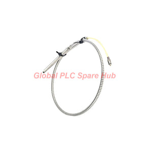


Bently Nevada 21505-00-60-05-02 | 7200 Series Precision Vibration Probe
Manufacturer: Bently Nevada
Product No.: 21505-00-60-05-02
Condition: In stock
Product Type: Proximity Probe
Product Origin: USA
Payment: T/T, Western Union
Weight: 323g
Shipping port: Xiamen
Warranty: 12 months
Estimate delivery times: 12-26 days (International), 3-6 days (United States).
Return within 30 days of purchase. Duties & taxes are non-refundable.
Guaranteed Safe Checkout
21505-00-60-05-02 Bently Nevada 7200 Proximity Vibration Probe
The Bently Nevada 21505-00-60-05-02 is an 8 mm proximity probe for non-contact displacement and vibration measurement. It belongs to the 7200 Proximity Transducer System and uses a 3/8-24 threaded mounting configuration. Its stainless-steel armored lead helps protect the cable in demanding machinery installations.
This configuration includes a 0.5 m total length and a miniature male coaxial connector. Engineers can use it for shaft vibration monitoring and relative shaft displacement measurement when the complete transducer system matches the required electrical characteristics.
- Manufacturer: Bently Nevada
- Model: 21505-00-60-05-02
- Series: 7200 Proximity Transducer Systems
- Product type: Proximity vibration probe
- Condition: New and original in factory packing
- Factory warranty: 12 months
01 | Configuration Breakdown — Read the Suffix Before Ordering
Use the following configuration tree to verify the requested assembly against the existing installation.
21505 - 00 - 60 - 05 - 02
  │      │    │    │    └── 02: Miniature male coaxial connector
  │      │    │    └─────── 05: 0.5 m total length (20 in)
  │      │    └──────────── 60: 6.0 in overall case length
  │      └───────────────── 00: 0.0 in unthreaded length
  └──────────────────────── 21505: 7200 proximity probe family
Construction details:
- Probe diameter: 8 mm
- Thread: 3/8-24
- Case: Standard configuration
- Lead armor: Stainless steel armor
- Connector: Miniature male coaxial connector
Engineering check: Confirm the installed probe's thread, case geometry, cable routing, connector interface, and required target gap. Do not assume that a matching model-family name guarantees interchangeability.
02 | Technical Data at a Glance
| Parameter | Specification | Engineering significance |
|---|---|---|
| Power supply | -17.5 to -26 VDC | Verify the compatible driver or Proximitor supply before connection. |
| Maximum power consumption | 12 mA | Check supply capacity and system wiring requirements. |
| Calibrated range | 80 mils (2.0 mm) | Defines the specified displacement measurement range. |
| Range start | Approximately 10 mils (0.25 mm) from the probe face | Set the target gap using the applicable system calibration procedure. |
| Scale factor | 200 mV/mil (7.87 V/mm), ±4% when calibrated as a system | Important for converting output voltage into displacement. |
| Interchangeability accuracy | Within ±9.5%, including interchangeability errors | Consider this tolerance when replacing a probe without full system calibration. |
| Linearity | Within 0.8 mil (0.02 mm) when calibrated as a system | Relevant to measurement accuracy across the calibrated range. |
| Linearity including interchangeability | Within 2.3 mils (0.06 mm) | Allow for additional error when components are interchanged. |
| Frequency response | 0–10 kHz; -5% at 10 kHz | Supports vibration measurements within the specified response range. |
| Temperature sensitivity | Source data indicates a scale-factor change at +65°C and a 1.27 mm gap; exact value requires verification. | Confirm the official specification before using temperature compensation calculations. |
| Proximitor operating temperature | -51°C to +100°C | Applies to the Proximitor, not automatically to the probe assembly. |
| Probe and extension cable temperature | -34°C to +177°C | Check actual ambient and cable exposure temperatures. |
| Relative humidity | Up to 95%, noncondensing | Prevent condensation and protect connectors from moisture ingress. |
| System weight | 0.59 kg (1.3 lb) | Source-listed system weight; verify the shipping or assembly weight if required. |
Data verification note: The supplied temperature-sensitivity figure contains a corrupted numeric value. This page does not infer or publish a replacement value. Confirm it against the applicable manufacturer documentation before engineering calculations.
03 | Measurement Principle and Diagnostic Value
The probe forms part of a proximity transducer system. The compatible driver converts the probe's interaction with a conductive target into an electrical signal that represents target displacement.
- Shaft vibration: Supplies a displacement signal for monitoring relative shaft motion when installed with a compatible driver and monitoring channel.
- Shaft position trends: Helps engineers compare displacement trends against established machine baselines.
- Vibration investigation: Provides input for investigating changes associated with rotor vibration, bearing behavior, or operating-condition changes.
- Signal-chain checks: Supports troubleshooting when engineers compare probe output, gap voltage, driver compatibility, cabling, and monitor readings.
Diagnostic limitation: The probe alone does not identify a specific fault or provide a complete machinery-protection function. Reliable diagnosis requires suitable signal conditioning, correct installation, monitor configuration, and operating-history analysis.
04 | Suitable Equipment and Applications
| Equipment or application | Potential use | Pre-installation check |
|---|---|---|
| Industrial turbines | Relative shaft vibration and displacement monitoring | Confirm target material, mounting geometry, system compatibility, and required monitoring range. |
| Centrifugal compressors | Rotor vibration monitoring and trend analysis | Verify probe location, cable routing, and the complete transducer's frequency response. |
| Pumps and rotating machinery | Non-contact shaft-motion measurement | Confirm shaft surface suitability and the machine manufacturer's sensor arrangement. |
| Gearboxes and high-speed rotating equipment | Displacement signal input for condition monitoring | Check target runout, mechanical clearance, and the required measurement bandwidth. |
| Existing 7200 monitoring installations | Replacement of a compatible probe assembly | Match the complete part number, driver, connector, cable arrangement, and calibration requirements. |
Application suitability depends on the complete installation design. Confirm the system architecture and the machine's monitoring requirements before selecting this probe for a protection loop.
05 | Installation and Commissioning Checks
- Verify the part number: Match all suffixes with the existing assembly and installation drawing.
- Inspect the mounting point: Check the 3/8-24 thread, available clearance, and mechanical condition before installation.
- Inspect the armored lead: Check for crushed sections, sharp bends, damaged armor, and connector contamination.
- Confirm driver compatibility: Verify the probe and driver combination against the manufacturer's system documentation.
- Set the target gap: Follow the approved system calibration procedure rather than relying on physical spacing alone.
- Check the signal: Compare gap voltage, displacement output, and monitor readings with the commissioning baseline.
- Record the baseline: Document installation details and initial readings to support future fault investigation.
Do not connect the probe directly to a PLC analog input unless the interface design includes the required compatible signal conditioning. Verify the actual output interface before wiring.
06 | Global PLC Spare HUB’s Insight
During a probe replacement, engineers should verify the entire measurement chain rather than matching only the probe diameter. A different cable length, connector, driver, or calibration arrangement can affect installation and signal interpretation.
For example, if a vibration monitor reports an unexpected displacement after maintenance, first check the connector seating, cable condition, driver compatibility, and gap voltage. Then compare the installed configuration with the original commissioning record. This sequence helps separate installation errors from genuine changes in machine behavior.
For critical rotating equipment, preserve the existing measurement baseline whenever possible. If a replacement introduces different interchangeability tolerances, follow the approved recalibration procedure before relying on alarm or trip thresholds.
07 | Selection Comparison: 21505-00-60-05-02 vs. 21505-22-55-10-02
Compare the requested probe with the following alternative before placing an order:
Alternative model: 21505-22-55-10-02 Bently Nevada 7200 Series Proximity Vibration Probe
| Selection item | 21505-00-60-05-02 | 21505-22-55-10-02 |
|---|---|---|
| Series | 7200 Proximity Transducer Systems | 7200 Series, based on the supplied product reference |
| Unthreaded length | 00: 0.0 in | Must be verified against the applicable manufacturer documentation. |
| Overall case length | 60: 6.0 in | Must be verified against the applicable manufacturer documentation. |
| Total length | 05: 0.5 m (20 in) | Must be verified against the applicable manufacturer documentation. |
| Connector option | 02: Miniature male coaxial connector | Must be verified against the applicable manufacturer documentation. |
| Recommended selection basis | Use when the documented mounting dimensions, lead length, and connector match the existing installation. | Choose only after confirming its full suffix configuration and compatibility with the installed system. |
Technical recommendation: Do not select the alternative based on the shared 21505 model prefix alone. Obtain its official suffix definitions and compare mounting dimensions, total length, connector type, and driver compatibility. If the existing installation uses the 00-60-05-02 configuration, the same complete part number is the more straightforward replacement candidate, subject to verification of the original system documentation.
08 | Maintenance and Troubleshooting Guidance
- Unexpected vibration readings: Check the probe gap, connector seating, cable integrity, driver compatibility, and monitor channel configuration.
- Unstable output: Inspect the armored lead and connectors for mechanical damage or contamination. Compare readings with the baseline before changing alarm settings.
- Inconsistent replacement readings: Verify the installed part number and calibration method. Account for interchangeability tolerances where applicable.
- Temperature-related concerns: Compare actual probe, cable, and driver temperatures with their respective limits. Do not apply the driver temperature range to the probe assembly.
- Suspected sensor failure: Isolate the fault through approved maintenance procedures and compatible test equipment. Do not condemn the probe solely from a monitor alarm.
09 | Packaging, Warranty, and Shipping
- Product condition: New and original in factory packing.
- Warranty: 12-month factory warranty, subject to the applicable purchase terms.
- Shipping methods: FedEx, UPS, and DHL, subject to destination and service availability.
- Order verification: Confirm the full part number and required configuration before shipment.
10 | Frequently Asked Questions
Q1. What information should I provide when requesting a replacement quotation?
Provide the complete part number, installed driver model, connector details, cable arrangement, and machine application. A photo of the nameplate and mounting point can help confirm configuration details.
Q2. Can I replace the probe without recalibrating the monitoring channel?
Do not assume recalibration is unnecessary. Review the manufacturer’s replacement procedure and interchangeability tolerances. Follow site requirements for verifying gap voltage, signal scaling, alarm thresholds, and baseline readings.
Q3. How can I distinguish a probe problem from a monitor-channel problem?
Compare the probe assembly, driver, wiring, and channel configuration systematically. Use approved test procedures and known-good compatible components where permitted. A single abnormal monitor reading does not prove the probe has failed.
Q4. What should I check when the replacement fits mechanically but produces different readings?
Check the complete suffix configuration, driver compatibility, target gap, cable condition, and calibration settings. Also review shaft surface condition and electrical interference before attributing the difference to sensor failure.
Q5. Is this probe suitable for every Bently Nevada 7200 installation?
No. A shared series designation does not establish full interchangeability. Confirm the driver, connector, mounting dimensions, required cable length, measurement range, and monitoring-system documentation before ordering.
Request a Quote
Contact Global PLC Spare HUB with the complete model number 21505-00-60-05-02 and your application requirements. Our team can help review the supplied configuration details and shipping options before you order.
Tags
Q: Are these parts 100% original and new?
A: Yes. Every component is guaranteed to be 100% original, brand-new, and factory-sealed. We also provide a 12-month comprehensive warranty for your peace of mind.
Q: How fast is the shipping to my country?
A: For in-stock items, we offer same-day dispatch. International express shipping (DHL/FedEx/UPS) typically delivers within 3–5 business days worldwide.
Q: Can I get a formal quotation with shipping costs?
A: Absolutely. Our sales team is ready to provide a detailed Proforma Invoice (PI) including the most competitive shipping rates for your location.
Q: Do you offer discounts for bulk orders?
A: We provide volume-based pricing for large projects or multiple-item orders. Please contact us to get our Best Price Guarantee.
12-Month Comprehensive Warranty
Every part supplied by Global PLC Spare Hub is covered by a 12-month warranty from the date of invoice.
- Coverage: Functional defects and hardware failures under normal operating conditions.
- Commitment: We provide immediate repair, replacement, or a full refund for any verified defective components to minimize your operational downtime.
Returns & Exchange Policy
We offer a 30-day return policy to ensure you receive the exact part your system requires.
- Eligibility: Returns are accepted for uninstalled items in their original, factory-sealed packaging.
- RMA Process: Please contact our support team to obtain a Return Merchandise Authorization (RMA) number before shipping.
- Fast Processing: Refunds or exchanges are processed within 3–5 business days after the returned item passes our technical inspection.
Need Technical Assistance?Not sure if this part is compatible with your system? [Consult our Engineers] before purchasing to ensure 100% compatibility.
People Also Bought


