


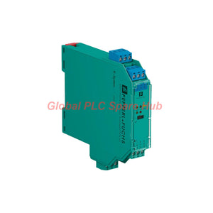
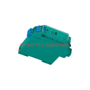
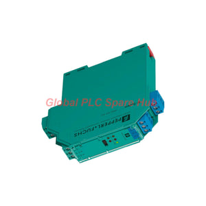
KFD2-SL2-Ex2 Pepperl+Fuchs Dual Channel Barrier KFD2 Series
Manufacturer: Pepperl+Fuchs
Product No.: KFD2-SL2-Ex2
Condition: In stock
Product Type: Dual Channel Barrier
Product Origin: DE
Payment: T/T, Western Union
Weight: 150g
Shipping port: Xiamen
Warranty: 12 months
Estimate delivery times: 12-26 days (International), 3-6 days (United States).
Return within 30 days of purchase. Duties & taxes are non-refundable.
Guaranteed Safe Checkout
Product Overview | Dual-Channel Solenoid Control
The Pepperl+Fuchs KFD2-SL2-Ex2 is a two-channel isolated solenoid driver for industrial hazardous-area applications. It converts control-side logic signals into intrinsically safe output signals for compatible field loads.
Each channel provides a dedicated field-side output connection. The module accepts non-polarized logic inputs and operates from a 20–30 V DC supply. Its output delivers up to 45 mA at a minimum voltage of 11.7 V under the specified operating conditions.
Integrated Line Fault Detection (LFD) monitors field wiring for open circuits and short circuits. DIP switches provide configuration options, while front-panel LEDs support local status checks.
The KFD2 Series architecture combines dual-channel signal isolation, intrinsically safe output circuits, and functional safety capabilities. The module supports applications up to SIL 2 according to IEC/EN 61508.
01 | Product Identity and Functional Highlights
| Identification | Specification |
|---|---|
| Manufacturer | Pepperl+Fuchs |
| Model | KFD2-SL2-Ex2 |
| Product Family | KFD2 Series |
| Product Type | Solenoid Driver / Isolated Barrier |
| Channel Configuration | 2 Independent Channels |
| Signal Classification | Digital Output |
| Control Input | Non-Polarized Logic Input |
| Field Output | Intrinsically Safe Driver Output |
| Supply Voltage | 20–30 V DC |
| Maximum Output Current | 45 mA |
| Minimum Output Voltage | 11.7 V DC at the specified output load |
| Line Monitoring | Integrated LFD |
| Configuration | DIP Switches |
| Local Indication | LED Indicators |
| Functional Safety | Up to SIL 2 |
02 | Electrical Interface and Signal Specifications
A. Power Supply
- Rated operating voltage: 20–30 V DC.
- Power connection: Power Rail or terminals 14+ and 15-.
- Maximum power consumption: 3.3 W at 45 mA output current.
- Maximum safe voltage Um: 40 V.
B. Control-Side Logic Input
| Input Parameter | Specification |
|---|---|
| Connection Side | Control Side |
| Terminals | 7, 8, 9 |
| Input Configuration | Non-Polarized |
| Input Current | Approximately 3 mA at 24 V DC |
| Logic 1 Signal | 16–30 V DC |
| Logic 0 Signal | 0–5 V DC |
C. Field-Side Output
| Output Parameter | Specification |
|---|---|
| Connection Side | Field Side |
| Channel 1 | Terminals 1+, 2-, 3 |
| Channel 2 | Terminals 4+, 5-, 6- |
| Internal Resistance Ri | 272 Ω |
| Output Current Ie | ≤ 45 mA |
| Output Voltage Ue | ≥ 11.7 V |
| Open-Circuit Voltage Us | Minimum 24 V |
| Energized Delay | ≤ 20 ms |
| De-Energized Delay | ≤ 20 ms |
The output values apply to rated operating voltages between 20 and 30 V DC. Verify the field load requirements before connecting the solenoid or actuator.
03 | Line Fault Detection and Diagnostic Characteristics
The integrated LFD function monitors the field-side output circuit. It helps maintenance teams distinguish wiring faults from normal switching conditions.
| Diagnostic Condition | Detection Threshold |
|---|---|
| Open Circuit | Resistance > 10 kΩ |
| Short Circuit | Resistance < 50 Ω |
| Test Current | < 650 µA |
04 | Intrinsic Safety and Functional Safety
The KFD2-SL2-Ex2 provides intrinsically safe output circuits for compatible hazardous-area loads. Its field-side electrical parameters define the permitted connection conditions.
| Intrinsic Safety Parameter | Specification |
|---|---|
| Protection Concept | Ex ia |
| Gas Group | IIC |
| Maximum Output Voltage Uo | 28 V |
| Maximum Output Current Io | 110 mA |
| Maximum Output Power Po | 770 mW |
| Output Characteristic | Linear |
| Maximum Safe Supply Voltage Um | 40 V |
| Functional Safety Level | Up to SIL 2 |
| Safety Standard | IEC/EN 61508 |
Important Parameter Distinction:
- Uo, Io, and Po describe intrinsic safety output parameters.
- Us, Ie, and Ue describe normal output operating characteristics.
- Um specifies the maximum safe voltage for the supply circuit.
- These values serve different engineering purposes and are not interchangeable.
For safety instrumented applications, verify the complete safety function and its system-level calculations. The module's SIL capability alone does not establish the SIL rating of the complete installation.
05 | Galvanic Isolation and Electrical Protection
The module separates the control input, power supply, and field output circuits through reinforced insulation.
| Isolation Interface | Insulation Specification |
|---|---|
| Input / Output | Reinforced insulation |
| Input / Power Supply | Reinforced insulation |
| Power Supply / Output | Reinforced insulation |
| Rated Insulation Voltage | 300 Veff |
| Reference Standard | IEC/EN 61010-1 |
This isolation architecture helps separate control-side logic signals from field-side hazardous-area circuits. It also reduces direct electrical coupling between the connected circuit sections.
06 | Installation and Terminal Configuration
Terminal Connection Reference
| Terminal | Function |
|---|---|
| 1+, 2-, 3 | Channel 1 Field Output |
| 4+, 5-, 6- | Channel 2 Field Output |
| 7, 8, 9 | Control-Side Logic Input |
| 14+, 15- | DC Power Supply |
Mounting Requirements
- Mount the module on a 35 mm DIN rail according to EN 60715.
- Use the Power Rail system or designated supply terminals.
- Check terminal assignments against the wiring diagram.
- Maintain suitable cabinet ventilation.
- Keep field wiring separate from unrelated power circuits.
- Observe hazardous-area wiring and segregation requirements.
Power Rail Installation
The module supports Power Rail supply distribution. This arrangement can simplify cabinet power wiring when several compatible interface modules share the same supply system.
Check Power Rail compatibility and current capacity before installation. Do not assume that every KFD2 module uses the same rail configuration.
07 | DIP Switch Configuration and Commissioning
The module provides DIP switches for configuration. Front-panel LEDs help technicians inspect operating conditions during commissioning.
Recommended Commissioning Procedure
- Verify the complete model designation.
- Check the available DC supply voltage.
- Inspect the control-side logic input wiring.
- Confirm the required DIP switch settings using the manufacturer's manual.
- Check both field output connections independently.
- Test each channel with its intended field load.
- Verify the LFD response under approved test conditions.
- Confirm the receiving system recognizes the correct output states.
Maintenance Recommendations
- Inspect screw terminals for loose connections.
- Check field cable insulation and continuity.
- Review abnormal LED indications.
- Verify output voltage under the actual connected load.
- Check DIP switch positions after cabinet maintenance.
- Record functional test results for safety-related applications.
Always use the manufacturer's configuration table for DIP switch assignments. Do not change safety-related settings without reviewing the approved application design.
08 | Mechanical and Environmental Specifications
| Parameter | Specification |
|---|---|
| Operating Temperature | -20 to +50 °C |
| Protection Rating | IP20 |
| Connection Type | Screw Terminals |
| Housing Type | B2 |
| Dimensions (W × H × D) | 20 × 119 × 115 mm |
| Weight | Approximately 150 g |
| Mounting | 35 mm DIN Rail |
| Local Indicators | LEDs |
| Configuration Elements | DIP Switches |
The IP20 housing suits protected industrial control cabinets. It does not provide protection against water or conductive dust.
09 | Certifications and Regulatory Compliance
| Certification Item | Reference |
|---|---|
| EU-Type Examination Certificate | ZELM 00 ATEX 0024 |
| Gas Protection Marking | II (1)G [Ex ia Ga] IIC |
| Dust Protection Marking | II (1)D [Ex ia Da] IIIC |
| Mining Protection Marking | I (M1) [Ex ia Ma] I |
| EMC Directive | 2014/30/EU |
| EMC Standard | EN 61326-1:2013 |
| EMC Recommendation | NE 21:2006 |
| Electrical Safety | EN 61010-1:2010 |
| Protection Rating Standard | IEC 60529:2001 |
| Functional Safety | IEC/EN 61508 |
Check the current certificate documentation before hazardous-area installation. Confirm the approved application, gas group, and installation conditions.

Tags
Q: Are these parts 100% original and new?
A: Yes. Every component is guaranteed to be 100% original, brand-new, and factory-sealed. We also provide a 12-month comprehensive warranty for your peace of mind.
Q: How fast is the shipping to my country?
A: For in-stock items, we offer same-day dispatch. International express shipping (DHL/FedEx/UPS) typically delivers within 3–5 business days worldwide.
Q: Can I get a formal quotation with shipping costs?
A: Absolutely. Our sales team is ready to provide a detailed Proforma Invoice (PI) including the most competitive shipping rates for your location.
Q: Do you offer discounts for bulk orders?
A: We provide volume-based pricing for large projects or multiple-item orders. Please contact us to get our Best Price Guarantee.
12-Month Comprehensive Warranty
Every part supplied by Global PLC Spare Hub is covered by a 12-month warranty from the date of invoice.
- Coverage: Functional defects and hardware failures under normal operating conditions.
- Commitment: We provide immediate repair, replacement, or a full refund for any verified defective components to minimize your operational downtime.
Returns & Exchange Policy
We offer a 30-day return policy to ensure you receive the exact part your system requires.
- Eligibility: Returns are accepted for uninstalled items in their original, factory-sealed packaging.
- RMA Process: Please contact our support team to obtain a Return Merchandise Authorization (RMA) number before shipping.
- Fast Processing: Refunds or exchanges are processed within 3–5 business days after the returned item passes our technical inspection.
Need Technical Assistance?Not sure if this part is compatible with your system? [Consult our Engineers] before purchasing to ensure 100% compatibility.
People Also Bought


