


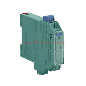
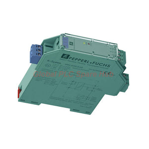
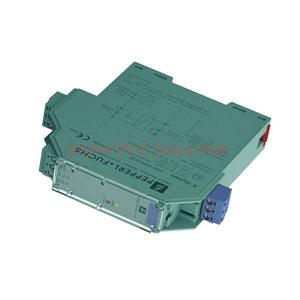
KFD2-SCD2-Ex1.LK Pepperl+Fuchs K-System HART Analog Output Barrier
Manufacturer: Pepperl+Fuchs
Product No.: KFD2-SCD2-Ex1.LK
Condition: In stock
Product Type: Analog Output Barrier
Product Origin: DE
Payment: T/T, Western Union
Weight: 150g
Shipping port: Xiamen
Warranty: 12 months
Estimate delivery times: 12-26 days (International), 3-6 days (United States).
Return within 30 days of purchase. Duties & taxes are non-refundable.
Guaranteed Safe Checkout
Product Identification | SMART Current Driver
KFD2-SCD2-Ex1.LK is a single-channel SMART Current Driver manufactured by Pepperl+Fuchs. It belongs to the K-System isolated barrier family.
This analog output interface transfers 4–20 mA control signals to compatible field instruments. It supports HART communication between control equipment and intelligent field devices.
The module drives compatible I/P converters, solenoid interfaces, and valve positioners. Its isolated signal path supports hazardous-area applications requiring intrinsically safe field circuits.
Integrated Line Fault Detection monitors field wiring conditions. Dedicated test points simplify electrical measurements during commissioning and maintenance.
Technical Profile | Key Specifications
| Manufacturer | Pepperl+Fuchs |
| Model | KFD2-SCD2-Ex1.LK |
| Product Family | K-System |
| Product Type | SMART Current Driver / Isolated Barrier |
| Signal Classification | Analog Output |
| Channel Configuration | 1-channel |
| Input Signal | 4–20 mA |
| Output Signal | 4–20 mA |
| Communication | Bidirectional HART Transparent Transmission |
| Maximum Output Load | 700 Ω |
| Maximum Input Current | Approximately 25 mA |
| Power Supply | 10–35 V DC |
| Functional Safety | Up to SIL 2 (SC 3) |
| Hazardous Area Protection | Intrinsic Safety [Ex ia] |
| Mounting | DIN Rail |
| Protection Rating | IP20 |
Signal Engineering | Input and Output Characteristics
Control-Side Input
| Connection Terminals | 7-, 8+, (9+) |
| Input Signal Range | 4–20 mA |
| Current Limitation | Approximately 25 mA |
| Voltage Drop | Approximately 4 V |
| Equivalent Internal Resistance | 200 Ω at 20 mA |
| Input Resistance | > 100 kΩ under specified field wiring conditions |
Field-Side Analog Output
| Connection Terminals | 1+, 2- |
| Output Signal | 4–20 mA |
| Permitted Load | 100–700 Ω |
| Output Voltage | ≥ 14 V at 20 mA |
| HART Transmission | Bidirectional and transparent |
| Line Fault Detection | Supported |
The 700 Ω maximum load provides flexibility for compatible field circuits. Engineers should include cable resistance and connected instrument impedance in the total load calculation.
Dynamic Performance | Accuracy and Response
| Deviation After Calibration | 10 µA at 293 K (20 °C) |
| Included Error Components | Non-linearity, calibration, hysteresis, supply and load changes |
| Temperature Influence | 1 µA/°C |
| Rise Time | < 100 µs |
| Measurement Transition | 10–90% |
The specified deviation represents the combined error after calibration. It includes several electrical influence factors.
Engineering Note: The detailed specifications provide a 10 µA deviation value. Do not interpret this figure as a separately specified linearity or resolution value.
HART Communication | Smart Field Device Integration
- Transparent Communication: Supports bidirectional HART signal transmission.
- Smart I/P Converters: Transfers analog control signals to compatible intelligent converters.
- Valve Positioners: Supports compatible HART-enabled valve positioning devices.
- Parameter Access: Allows supported field-device communication through the signal interface.
- Maintenance Support: Helps technicians access compatible smart instrument information.
HART communication uses digital signals superimposed on the analog current loop. Verify the field instrument and control system support the required communication configuration.
Power Architecture | Supply and Consumption
| Supply Connection | Power Rail or Terminals 14+, 15- |
| Rated Supply Voltage | 10–35 V DC |
| Supply Ripple | Within supply tolerance |
| Power Loss | 0.8 W |
| Power Consumption | 1 W at 20 mA |
The module supports Power Rail installation or direct terminal connections. Confirm the selected supply arrangement before panel wiring.
Intrinsic Safety | Hazardous Area Parameters
| EC-Type Examination Certificate | BAS 00 ATEX 7240 |
| Additional Conformity Statement | TÜV 99 ATEX 1499 X |
| Equipment Group | II (1)GD, I (M1) |
| Gas Protection | [Ex ia] IIC |
| Dust Protection | [Ex iaD] |
| Mining Protection | [Ex ia] I |
| Output Protection | Ex ia IIC, Ex iaD |
| Output Voltage Uo | 25.2 V |
| Output Current Io | 93 mA |
| Output Power Po | 585 mW |
| Maximum Safe Supply Voltage Um | 250 V RMS |
| Maximum Safe Input Voltage Um | 250 V RMS |
| Zone Application | Compatible circuits in Zones 0, 1, and 2 |
Additional Zone 2 Classification
- Certificate: TÜV 99 ATEX 1499 X.
- Marking: II 3G Ex nA II T4.
- Application: Device installation in Zone 2, subject to certification conditions.
Important: Um represents the maximum safe voltage, not the normal operating supply voltage. Uo, Io, and Po define intrinsic safety assessment limits. Verify the complete field loop before installation.
Mechanical Construction | Installation Data
| Housing Type | B2 |
| Dimensions (W × H × D) | 20 × 124 × 115 mm |
| Weight | Approximately 150 g |
| Operating Temperature | -20 to +60 °C (-4 to +140 °F) |
| Protection Rating | IP20 |
| Electrical Connection | Terminals |
| Mounting | DIN Rail |
| Power Rail | Supported |
| Diagnostic Test Points | Available |
Functional Applications | Where to Use This Module
- Control Valve Positioning: Transmits analog commands to compatible smart valve positioners.
- Intelligent I/P Conversion: Interfaces 4–20 mA control signals with compatible HART-enabled I/P converters.
- Process Control: Supports analog output channels in PLC and DCS installations.
- Hazardous Area Instrumentation: Provides an intrinsically safe interface for compatible field equipment.
- Remote Valve Operation: Transfers control signals to suitable pneumatic valve systems.
- Smart Instrument Maintenance: Supports transparent HART communication for compatible field instruments.
Installation & Commissioning | Field Engineering Guide
Terminal Identification
| Terminal | Function |
| 7-, 8+, (9+) | Control-side analog input |
| 1+, 2- | Field-side current output |
| 14+, 15- | Auxiliary DC supply |
Approvals & Regulatory Compliance
- ATEX: BAS 00 ATEX 7240.
- ATEX Conformity Statement: TÜV 99 ATEX 1499 X.
- IECEx: IECEx BAS 04.0014.
- UL / cULus: Control Drawing 116-0173.
- EMC Directive: 2004/108/EC.
- EMC Standard: EN 61326-1:2006.
- EMC Recommendation: NE 21.
- Insulation Coordination: EN 50178.
- Electrical Isolation: EN 50178.
- Protection Standard: IEC 60529.
- Explosion Protection: EN 60079-0:2006, EN 60079-11:2007, EN 60079-15:2005, EN 61241-11:2006.
Supply Package & Commercial Information
| Manufacturer | Pepperl+Fuchs |
| Model | KFD2-SCD2-Ex1.LK |
| Product Description | SMART Current Driver |
| Package Quantity | 1 × Isolated Barrier |
| Product Condition | New & Original in Factory Packing |
| Warranty | Factory Warranty: 12 Months |
| Shipping Methods | FedEx, UPS, DHL |
| Availability | Contact us for current stock information |
Supplied accessories and documentation depend on the actual factory package configuration.

Tags
Q: Are these parts 100% original and new?
A: Yes. Every component is guaranteed to be 100% original, brand-new, and factory-sealed. We also provide a 12-month comprehensive warranty for your peace of mind.
Q: How fast is the shipping to my country?
A: For in-stock items, we offer same-day dispatch. International express shipping (DHL/FedEx/UPS) typically delivers within 3–5 business days worldwide.
Q: Can I get a formal quotation with shipping costs?
A: Absolutely. Our sales team is ready to provide a detailed Proforma Invoice (PI) including the most competitive shipping rates for your location.
Q: Do you offer discounts for bulk orders?
A: We provide volume-based pricing for large projects or multiple-item orders. Please contact us to get our Best Price Guarantee.
12-Month Comprehensive Warranty
Every part supplied by Global PLC Spare Hub is covered by a 12-month warranty from the date of invoice.
- Coverage: Functional defects and hardware failures under normal operating conditions.
- Commitment: We provide immediate repair, replacement, or a full refund for any verified defective components to minimize your operational downtime.
Returns & Exchange Policy
We offer a 30-day return policy to ensure you receive the exact part your system requires.
- Eligibility: Returns are accepted for uninstalled items in their original, factory-sealed packaging.
- RMA Process: Please contact our support team to obtain a Return Merchandise Authorization (RMA) number before shipping.
- Fast Processing: Refunds or exchanges are processed within 3–5 business days after the returned item passes our technical inspection.
Need Technical Assistance?Not sure if this part is compatible with your system? [Consult our Engineers] before purchasing to ensure 100% compatibility.
People Also Bought


