


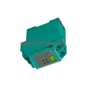
KFD2-DWB-1.D Speed Monitoring Relay | Pepperl+Fuchs K-System
Manufacturer: Pepperl+Fuchs
Product No.: KFD2-DWB-1.D
Condition: In stock
Product Type: Rotation Speed Monitor
Product Origin: DE
Payment: T/T, Western Union
Weight: 150g
Shipping port: Xiamen
Warranty: 12 months
Estimate delivery times: 12-26 days (International), 3-6 days (United States).
Return within 30 days of purchase. Duties & taxes are non-refundable.
Guaranteed Safe Checkout
Product Overview | Frequency-Based Rotation Monitoring
Pepperl+Fuchs KFD2-DWB-1.D is a single-channel rotation speed monitor from the K-System signal conditioning range. It evaluates pulse frequency from NAMUR sensors, dry contacts, and compatible three-wire sensors. The unit converts measured frequency into relay-based switching signals for machinery protection and process control.
Unlike conventional digital switching amplifiers, this device performs continuous frequency measurement. Its measuring range extends from 0.001 Hz to 12 kHz. Engineers can configure switching thresholds through the integrated keypad and display.
Two independent relay outputs support overspeed and underspeed monitoring. A dedicated start-up override input helps prevent premature trips during machine acceleration. Integrated Line Fault Detection identifies sensor wiring failures before they compromise monitoring reliability.
The KFD2-DWB-1.D also supports safety-related applications up to SIL 2, subject to the complete system design and applicable safety requirements.
Technical Identity and Electrical Ratings
| Manufacturer | Pepperl+Fuchs |
| Model | KFD2-DWB-1.D |
| Product Family | K-System |
| Product Category | Rotation Speed Monitor / Frequency Signal Conditioner |
| Signal Classification | Digital Input |
| Input Channels | 1 Measurement Channel |
| Power Supply | 24 V DC Nominal |
| Rated Supply Range | 20–30 V DC |
| Rated Current | Approximately 100 mA |
| Power Consumption | 1.8 W Maximum |
| Power Dissipation | 1.8 W Maximum |
| Output Configuration | 2 Relay Outputs |
| Functional Safety | Up to SIL 2 |
| Operating Temperature | -20°C to +60°C |
| Protection Rating | IP20 |
| Mounting | 35 mm DIN Rail, EN 60715 |
| Housing Type | C2 |
| Dimensions | 40 × 119 × 115 mm (W × H × D) |
| Weight | Approximately 300 g |
Frequency Measurement and Signal Processing
Frequency measurement is the primary function of the KFD2-DWB-1.D. The device evaluates incoming sensor pulses and determines whether machine speed remains within configured limits.
| Measurement Range | 0.001–12,000 Hz |
| Measurement Resolution | 0.1% of measured value, minimum 0.001 Hz |
| Measurement Accuracy | 0.1% of measured value, above 0.001 Hz |
| Measurement Time | Less than 100 ms |
| Temperature Influence | 0.003%/K (30 ppm/K) |
| Output Response Delay | ≤ 200 ms |
| Input Pulse Duration | Greater than 50 μs |
These specifications help engineers evaluate low-speed detection, operating stability, and transient response. Actual system response also depends on sensor pulse characteristics and configured switching conditions.
Sensor Input and Start-Up Override
The field input accepts multiple sensor configurations. This flexibility supports different machine monitoring arrangements.
- NAMUR Sensors: Compatible with sensors according to EN 60947-5-6.
- Mechanical Contacts: Accepts suitable dry-contact pulse sources.
- Two-Wire Sensors: Connect through terminals 1+ and 3-.
- Three-Wire Sensors: Use terminals 1+, 2-, and 3 according to the wiring diagram.
| Input Connection | Input I: 1+, 2-, 3- |
| Open-Circuit Voltage | 22 V |
| Short-Circuit Current | 40 mA |
| Input Resistance | 4.7 kΩ |
| Logic 1 Threshold | Greater than 2.5 mA |
| Logic 0 Threshold | Less than 1.9 mA |
| Open-Circuit Detection | Current ≤ 0.15 mA |
| Short-Circuit Detection | Current > 4 mA |
Start-Up Override: A separate input allows temporary suppression of configured speed monitoring during machine acceleration. Engineers can set the override period from 1 to 1000 seconds, in one-second increments.
| Override Input | Terminals 13+ and 14- |
| Active Condition | Input Current > 4 mA for at least 100 ms |
| Passive Condition | Input Current < 1.5 mA |
| Open-Circuit Voltage | 18 V |
| Short-Circuit Current | 5 mA |
| Adjustment Range | 1–1000 seconds |
Dual Relay Architecture and Switching Performance
The control side contains two relay output groups. Each group provides contacts for external switching circuits.
| Relay Output I | Terminals 10, 11, 12 |
| Relay Output II | Terminals 16, 17, 18 |
| Maximum AC Contact Load | 250 V AC / 2 A / cos φ ≥ 0.7 |
| Maximum DC Contact Load | 40 V DC / 2 A |
| Operate Delay | Approximately 20 ms |
| Release Delay | Approximately 20 ms |
| Mechanical Life | 5 × 10⁷ switching cycles |
| Collective Fault Indication | Power Rail |
Engineers can assign relay functions according to the required monitoring logic. Typical applications include separate high-speed and low-speed alarm or trip circuits.
For inductive loads, verify the external suppression requirements and relay contact ratings. Do not exceed the specified switching voltage or current.
Galvanic Isolation and Functional Safety
Electrical isolation separates the measurement circuit from external control circuits. This arrangement helps reduce unwanted electrical interaction between connected equipment.
| Input I to Other Circuits | Reinforced insulation |
| Output I to Output II | Reinforced insulation |
| Output Circuits to Other Circuits | Reinforced insulation |
| Rated Insulation Voltage | 300 V RMS |
| Start-Up Override to Supply and Collective Error | Functional insulation |
| Functional Insulation Rating | 50 V RMS |
| Reference Standards | IEC/EN 61010-1 and IEC 62103 |
| Safety Integrity Level | Up to SIL 2 |
The module supports safety-related speed monitoring architectures. Engineers must assess the complete safety loop, including sensors, logic, outputs, diagnostics, and final switching elements.
Installation and Commissioning Workflow
Correct installation establishes reliable pulse acquisition and switching behavior. Follow the sequence below during system integration.
- Verify the Device: Confirm the KFD2-DWB-1.D model and terminal identification.
- Prepare the Rail: Install a compatible 35 mm DIN rail according to EN 60715.
- Connect the Supply: Apply 20–30 V DC to terminals 23+ and 24-. Power Rail supply is also supported.
- Wire the Sensor: Select the correct two-wire or three-wire input arrangement.
- Connect Override: Wire the start-up override signal to terminals 13+ and 14- when required.
- Connect Relays: Wire output groups through terminals 10–12 and 16–18.
- Configure Parameters: Set the required frequency thresholds and relay operating functions.
- Set Override Timing: Enter a suitable acceleration period for the monitored machine.
- Verify Operation: Test actual sensor pulses and confirm relay switching at the configured limits.
Engineering Precaution: Disconnect power before changing field wiring. Verify the sensor connection diagram and relay contact arrangement. Qualified personnel must perform installation and functional safety validation.
Maintenance and Fault Diagnosis
Periodic inspection helps identify measurement problems before they affect machinery operation.
| Observed Condition | Recommended Inspection |
| No frequency measurement | Check sensor power, pulse wiring, and input signal amplitude. |
| Unstable speed readings | Inspect sensor alignment, pulse consistency, and cable shielding. |
| Unexpected relay switching | Review configured thresholds, hysteresis-related behavior, and machine speed variations. |
| Input line fault | Check open circuits, short circuits, and terminal connections. |
| Start-up trip | Compare override timing with the actual acceleration period. |
| Power Rail fault indication | Inspect the supply distribution and connected module conditions. |
Keep a record of measured operating frequencies and configured switching limits. Compare these values during scheduled inspections to identify changes in machine behavior.
Compatibility and Replacement Considerations
The KFD2-DWB-1.D requires more than a basic supply and terminal match during replacement. Engineers should verify the complete measurement and control arrangement.
- Sensor Type: Confirm NAMUR, dry-contact, or compatible three-wire sensor operation.
- Frequency Range: Ensure the application remains within 0.001–12,000 Hz.
- Supply: Confirm 20–30 V DC or compatible Power Rail distribution.
- Relay Interface: Check contact ratings and external control circuit requirements.
- Start-Up Logic: Verify override input behavior and configured delay.
- Safety Requirements: Confirm SIL suitability and system-level certification requirements.
- Mechanical Fit: Check the 40 mm housing width and cabinet clearance.
A similar-looking K-System module may use different input functions or terminal assignments. Always compare the complete order designation and technical documentation before substitution.
Certifications and Environmental Compliance
| Functional Safety | SIL 2 |
| Safety Standards | IEC/EN 61508 and IEC/EN 61511 |
| EMC Directive | 2014/30/EU |
| EMC Standard | EN 61326-1:2013 |
| Low Voltage Directive | 2014/35/EU |
| Electrical Safety Standard | EN 61010-1:2010 |
| EMC Recommendation | NE 21:2006 |
| Protection Standard | IEC 60529:2001 |
| Hazardous-Area Certificate | PF 08 CERT 1216 X |
| Hazardous-Area Marking | II 3G Ex nA nC IIC T4 Gc |
| UL Approval | E223772 |
Hazardous-Area Note: The specified hazardous-area temperature range is -20°C to +50°C. The general operating range is -20°C to +60°C. Follow the applicable certificate conditions when installing the device in classified areas.
Package Contents
- 1 × Pepperl+Fuchs KFD2-DWB-1.D Rotation Speed Monitor
- Product identification information
Power Rail accessories, additional wiring components, and documentation depend on the confirmed order configuration.

Tags
Q: Are these parts 100% original and new?
A: Yes. Every component is guaranteed to be 100% original, brand-new, and factory-sealed. We also provide a 12-month comprehensive warranty for your peace of mind.
Q: How fast is the shipping to my country?
A: For in-stock items, we offer same-day dispatch. International express shipping (DHL/FedEx/UPS) typically delivers within 3–5 business days worldwide.
Q: Can I get a formal quotation with shipping costs?
A: Absolutely. Our sales team is ready to provide a detailed Proforma Invoice (PI) including the most competitive shipping rates for your location.
Q: Do you offer discounts for bulk orders?
A: We provide volume-based pricing for large projects or multiple-item orders. Please contact us to get our Best Price Guarantee.
12-Month Comprehensive Warranty
Every part supplied by Global PLC Spare Hub is covered by a 12-month warranty from the date of invoice.
- Coverage: Functional defects and hardware failures under normal operating conditions.
- Commitment: We provide immediate repair, replacement, or a full refund for any verified defective components to minimize your operational downtime.
Returns & Exchange Policy
We offer a 30-day return policy to ensure you receive the exact part your system requires.
- Eligibility: Returns are accepted for uninstalled items in their original, factory-sealed packaging.
- RMA Process: Please contact our support team to obtain a Return Merchandise Authorization (RMA) number before shipping.
- Fast Processing: Refunds or exchanges are processed within 3–5 business days after the returned item passes our technical inspection.
Need Technical Assistance?Not sure if this part is compatible with your system? [Consult our Engineers] before purchasing to ensure 100% compatibility.
People Also Bought


