


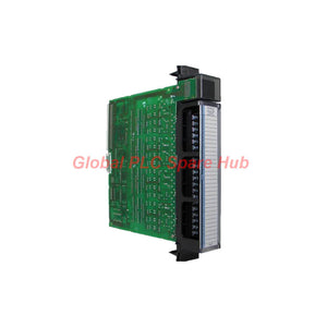
IC697MDL671 GE Fanuc Series 90-70 Interrupt Input Module
Manufacturer: GE Fanuc
Product No.: IC697MDL671
Condition: In stock
Product Type: Interrupt Input Module
Product Origin: USA
Payment: T/T, Western Union
Weight: 520g
Shipping port: Xiamen
Warranty: 12 months
Estimate delivery times: 12-26 days (International), 3-6 days (United States).
Return within 30 days of purchase. Duties & taxes are non-refundable.
Guaranteed Safe Checkout
IC697MDL671 GE Fanuc Series 90-70 Interrupt Input Module
The GE Fanuc IC697MDL671 is a 24 VDC interrupt input module designed for the Series 90-70 PLC platform. It monitors discrete field signals and supports interrupt-driven control applications where selected input events require prompt controller attention.
Unlike a conventional input module used only for routine status scanning, this module is intended for applications that depend on configured input events. It accepts signals from compatible switches, proximity sensors, and pushbuttons. Its 16 input positions are organized into four groups, with point assignments and configuration requirements that engineers must verify before wiring.
01 | How an Input Event Enters the Control System
Field device → 24 VDC input circuit → Input qualification → Interrupt event handling → PLC application logic
- Field event: A compatible switch, proximity sensor, or pushbutton changes its electrical state.
- Input qualification: The signal must meet the module's ON-state or OFF-state electrical thresholds. Input filtering, where supported and configured, can affect how short transitions are recognized.
- Interrupt handling: The module supports interrupt-oriented input processing for suitable control applications. Confirm the required configuration and controller programming method in the Series 90-70 documentation.
- Application response: The PLC program processes the event according to its configured logic. Actual response time depends on the complete controller configuration and application.
Engineering distinction: Interrupt capability does not automatically guarantee a fixed end-to-end response time. Sensor switching time, input qualification, module configuration, controller loading, and application logic all affect system response.
02 | Electrical Specification Map
| Specification | Value | Engineering consideration |
|---|---|---|
| Manufacturer | GE Fanuc | Confirm the installed Series 90-70 hardware configuration. |
| Series | Series 90-70 | Verify compatibility with the target rack and controller. |
| Catalog number | IC697MDL671 | Match the complete catalog number when sourcing a replacement. |
| Module type | Interrupt input module | Intended for configured interrupt-oriented discrete input applications. |
| Rated voltage | 24 VDC | Check the field supply under actual load conditions. |
| Input voltage range | -3 to 30 VDC | Use the specified logic thresholds to assess signal compatibility. |
| Input count | 16 positions | Not all positions should automatically be treated as standard field inputs. |
| Input arrangement | 4 groups of 4 | Point labels run from A1 through D4. |
| Input current | 10 mA listed | Confirm the applicable input-current specification for the operating voltage. |
| ON-state voltage | 13.5–30 VDC | Check that the field signal exceeds the required ON threshold. |
| OFF-state voltage, positive logic | -3 to 5 VDC | Assess residual voltage when the field device is OFF. |
| OFF-state voltage, negative logic | -5 to 30 VDC | Verify the configured logic mode and the manufacturer's definition of the threshold. |
| ON-state current | 6–15 mA | Check the field device's output capability. |
| OFF-state current | 0–2 mA | Consider leakage current from electronic sensors and switching devices. |
| Isolation voltage | 1500 V, as supplied | Verify the test conditions and isolation definition in the official manual. |
| Required current | 0.3 A, as supplied | Confirm the meaning, supply rail, and operating conditions before power-budget calculations. |
Specification note: The supplied data does not identify the reference conditions for every current and isolation value. Treat the listed figures as preliminary selection data and verify them against the applicable GE Fanuc documentation before final design approval.
03 | Point Allocation: Four Groups, Sixteen Positions
| Input group | Point labels | Planning guidance |
|---|---|---|
| Group A | A1–A4 | Check the individual point assignment and interrupt configuration. |
| Group B | B1–B4 | Map each field device to the correct rack and program reference. |
| Group C | C1–C4 | Verify wiring polarity and logic mode before commissioning. |
| Group D | D1–D4 | Reserve the last two positions for their documented configuration purpose. |
The supplied description identifies the last two positions in the final group as configuration inputs. Confirm the exact point labels and required states in the module manual before connecting field devices. Do not allocate these positions to normal process signals without verification.
04 | Where Engineers May Use the IC697MDL671
- Machine sequencing: Monitor selected discrete events that require interrupt-oriented processing within a Series 90-70 application.
- Position and limit monitoring: Interface with compatible limit switches and proximity sensors to report machine position or transition events.
- Operator command circuits: Process compatible pushbutton and selector-switch signals when the application requires the module's interrupt functionality.
- Equipment status monitoring: Capture discrete state changes from suitable auxiliary contacts and field devices.
- Legacy control-system maintenance: Replace a verified IC697MDL671 in an existing installation while preserving the documented hardware and program configuration.
These examples describe potential applications, not guaranteed suitability for every sensor or machine. Verify electrical compatibility, event timing, controller support, and application requirements before selecting the module.
05 | Commissioning and Fault-Isolation Workflow
| Check point | What to verify | Why it matters |
|---|---|---|
| 1. Module identity | Catalog number, hardware revision, and Series 90-70 configuration | Prevents replacement with a similar-looking but incompatible module. |
| 2. Field supply | Measure voltage at the input circuit during normal operation. | Confirms the signal reaches the required operating threshold. |
| 3. Logic polarity | Check positive or negative logic requirements against the wiring diagram. | A polarity mismatch can cause incorrect state interpretation. |
| 4. Input filtering | Review any supported filter settings and the signal's transition characteristics. | Filtering may suppress noise but can also affect recognition of short pulses. |
| 5. Interrupt configuration | Review the module setup, controller support, and application logic. | A valid electrical input alone does not prove that interrupt handling is configured correctly. |
| 6. Reserved positions | Confirm the documented use of the final two positions in Group D. | Prevents configuration points from being misused as ordinary inputs. |
Field symptoms and diagnostic direction
- Input event is not recognized: Measure the field voltage, inspect the signal path, and verify the ON-state threshold and logic polarity.
- Unexpected state changes occur: Check wiring integrity, field-device leakage, electrical noise, and any applicable input-filter settings.
- Signal is electrically valid but the expected action does not occur: Review interrupt configuration, controller compatibility, program logic, and event handling.
- Only some points behave incorrectly: Compare the affected point labels with the wiring schedule and configuration records before replacing the module.
- Events appear to be missed: Check whether the input pulse duration and event rate suit the documented module and controller response characteristics.
Use approved maintenance procedures when measuring live circuits or testing interrupt-driven logic. Do not assume that a field-device LED or an input-state indication alone proves the complete control sequence is functioning correctly.
06 | Global PLC Spare HUB's Insight
The IC697MDL671 should be selected according to its interrupt-input role, not simply its 24 VDC rating or 16-point count. A standard digital input module may not provide equivalent event-handling behavior, even when its electrical thresholds appear similar.
Before purchasing a replacement, compare the catalog number, rack configuration, point mapping, input polarity, and controller-program requirements. If the original application relies on short-duration signals, establish the required pulse width and event rate before approving the replacement.
For an existing installation, record the original point assignments and configuration settings before removing the module. After installation, test representative input transitions and confirm that the PLC application responds as intended. Validate the reserved configuration points against the official manual instead of inferring their function from the terminal labels alone.
07 | Condition, Warranty and Delivery
- Product: GE Fanuc IC697MDL671 Series 90-70 interrupt input module
- Condition: New and original in factory packing, subject to order confirmation
- Warranty: 12 months, subject to the seller's applicable warranty terms
- Shipping options: FedEx, UPS, or DHL, depending on destination and service availability
- Purchasing support: Provide the catalog number, controller or rack details, and application requirements to support a compatibility review.
08 | Frequently Asked Questions
Q1. What makes an interrupt input module different from a standard discrete input module?
Answer: An interrupt input module supports configured event handling rather than relying solely on routine input-state evaluation. The actual benefit depends on the controller, module setup, and program design. Confirm the supported interrupt mechanism in the system documentation before using it for time-sensitive sequences.
Q2. Can I use the IC697MDL671 with a sensor that has a 24 VDC output?
Answer: The rated supply voltage alone does not establish compatibility. Compare the sensor's output type, ON-state voltage, OFF-state leakage, current capability, and polarity with the module's requirements. Check the sensor datasheet and wiring diagram before connecting it.
Q3. How should I evaluate whether the module can detect a short pulse?
Answer: Determine the minimum pulse width and maximum event frequency required by the application. Then compare those requirements with the module's documented input qualification, filtering, and interrupt response behavior. Do not assume that every pulse within the broad voltage range will be detected.
Q4. Should all 16 positions be included in the field I/O count?
Answer: Not without checking the point assignment documentation. The supplied information identifies the last two positions in Group D as configuration-related. Confirm the exact reserved positions before preparing the I/O list or calculating usable field-input capacity.
Q5. What details help reduce replacement errors when sourcing an older Series 90-70 module?
Answer: Share the full IC697MDL671 catalog number, any visible revision details, the installed rack or controller model, and the original wiring or configuration records. Ask the supplier to confirm the item's condition, warranty, availability, and delivery method. For critical applications, complete a documented compatibility check before commissioning.
Tags
Q: Are these parts 100% original and new?
A: Yes. Every component is guaranteed to be 100% original, brand-new, and factory-sealed. We also provide a 12-month comprehensive warranty for your peace of mind.
Q: How fast is the shipping to my country?
A: For in-stock items, we offer same-day dispatch. International express shipping (DHL/FedEx/UPS) typically delivers within 3–5 business days worldwide.
Q: Can I get a formal quotation with shipping costs?
A: Absolutely. Our sales team is ready to provide a detailed Proforma Invoice (PI) including the most competitive shipping rates for your location.
Q: Do you offer discounts for bulk orders?
A: We provide volume-based pricing for large projects or multiple-item orders. Please contact us to get our Best Price Guarantee.
12-Month Comprehensive Warranty
Every part supplied by Global PLC Spare Hub is covered by a 12-month warranty from the date of invoice.
- Coverage: Functional defects and hardware failures under normal operating conditions.
- Commitment: We provide immediate repair, replacement, or a full refund for any verified defective components to minimize your operational downtime.
Returns & Exchange Policy
We offer a 30-day return policy to ensure you receive the exact part your system requires.
- Eligibility: Returns are accepted for uninstalled items in their original, factory-sealed packaging.
- RMA Process: Please contact our support team to obtain a Return Merchandise Authorization (RMA) number before shipping.
- Fast Processing: Refunds or exchanges are processed within 3–5 business days after the returned item passes our technical inspection.
Need Technical Assistance?Not sure if this part is compatible with your system? [Consult our Engineers] before purchasing to ensure 100% compatibility.
People Also Bought


