


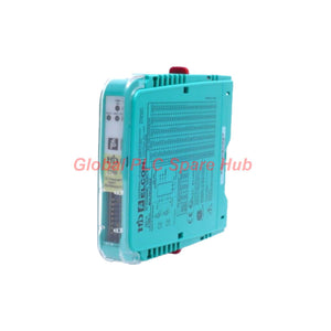
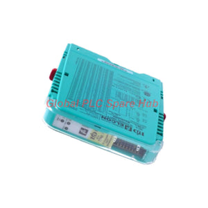
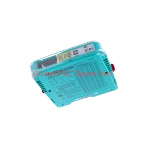
HiDMux2700 Pepperl+Fuchs 32-Channel HART Multiplexer Primary Module
Manufacturer: Pepperl+Fuchs
Product No.: HiDMux2700
Condition: In stock
Product Type: Multiplexer Primary Module
Product Origin: USA
Payment: T/T, Western Union
Weight: 140g
Shipping port: Xiamen
Warranty: 12 months
Estimate delivery times: 12-26 days (International), 3-6 days (United States).
Return within 30 days of purchase. Duties & taxes are non-refundable.
Guaranteed Safe Checkout
Pepperl+Fuchs HiDMux2700 Engineering Overview
The Pepperl+Fuchs HiDMux2700 functions as a high-density, 32-channel HART Multiplexer Primary Module engineered for continuous digital field device integration within H-System termination boards. Designed for non-intrinsically safe process loops, this primary module bridges analog 4–20 mA field instrumentation with asset management systems over a multi-drop RS-485 network. By consolidating up to 31 daisy-chained units on a single serial bus, control engineers can poll and configure up to 992 HART field transmitters (revisions 5 through 7) without interrupting critical process control signals.
System Architecture & Signal Integrity Highlights
- High-Density Loop Polling: Scans 32 individual HART channels per module with capacitive coupling (≤ 100 Ω output resistance) to ensure zero interference with standard 4–20 mA analog control loops.
- Multi-Drop Bus Scalability: Addresses 1 to 31 via side-mounted DIP switches, expanding single-port RS-485 host interfaces to manage nearly 1,000 smart field instruments.
- Robust 3-Port Galvanic Isolation: Separates RS-485 interface, 24 V DC power supply, and field channels up to 1000 Veff, reinforced by dual-capacitor isolation on every individual HART input.
- Safety & Hazardous Location Compliance: Rated up to SIL 3 per IEC/EN 61508 and certified for Zone 2 / Division 2 installation environments.
- Real-Time Loop Diagnostics: Front-panel LEDs provide immediate visual verification of power status (Green PWR ON), active bus traffic (Yellow HART TX), and field wiring anomalies (Red FAULT).
Comprehensive Technical Specifications
| Parameter Category | Technical Specification | Engineering Value / Standard |
|---|---|---|
| HART Field Interface | Supported Revisions & Channels | HART Rev. 5 to 7; 32 non-IS channels |
| Signal Characteristics | Input Voltage & Carrier Detect | 0.12 to 1.5 Vpp; Active > 0.12 Vpp / Inactive < 0.08 Vpp |
| Loop Impedance | Input Impedance & External Terminator | > 5 kΩ input; 230 to 500 Ω standard (up to 1000 Ω) |
| Transmit Amplitude | Load Dependent Output | 0.43–0.49 Vpp (200 Ω load); 1.1–1.2 Vpp (500 Ω load) |
| Transient Protection | Differential & Common Mode Clamping | ±5.2 V differential; ±10 V common mode (30 V max CMV) |
| RS-485 Host Bus | Baud Rate & Addressing | 9600, 19200, or 38400 bit/s (up to 57.6 kbaud); DIP 1–31 |
| Galvanic Isolation | Dielectric Withstand | 500 Vrms (Bus/Power); 1000 Veff (Bus/Field & Power/Field) |
| Power Supply | Rated Voltage & Dissipation | 20.4 to 30 V DC (24 V DC nominal); ~0.7 W dissipation |
| Environmental | Operating Temp & Humidity | -20 to 60 °C (-4 to 140 °F); 5 to 95% non-condensing |
| Physical Dimensions | Housing Size, Weight & Ingress | 18 × 114 × 130 mm (W × H × D); ~140 g; IP20 |
| Certifications | EMC & Functional Safety | IEC/EN 61508 (SIL 3); EN 61326-1:2013; NE 21:2012 |
Field Engineering & Commissioning FAQ
Q1: Why does the red FAULT LED illuminate during commissioning even when the 4–20 mA analog loop reads accurately at the DCS?
A1: A solid or flashing red FAULT indicator typically points to an open loop circuit, excessive line capacitance, or a missing/improperly sized loop resistor. While the analog current may still flow, the HART FSK signal requires a minimum loop resistance of 230 Ω to develop sufficient voltage swing (> 0.12 Vpp) for carrier detection. Verify that the termination board resistor falls within the 230–500 Ω window and check for loose shield drains.
Q2: How do we prevent communication collisions when daisy-chaining multiple multiplexers on a single RS-485 trunk?
A2: Before snapping the housing onto the H-System termination board, set a unique binary address (1 through 31) on the side-mounted DIP switches for every unit on the bus. Ensure all dip-switch baud rates match the host OPC server or asset management gateway, and install a 120 Ω line termination resistor across the differential RS-485 pair at the physical end of the trunk to suppress signal reflections.
Q3: Can this module be deployed directly inside Zone 1 hazardous areas to monitor intrinsically safe transmitters?
A3: No. This unit is engineered specifically for non-intrinsically safe field loops and carries Zone 2 / Division 2 approval. If your field transmitters reside in Zone 0 or Zone 1, you must route those signals through appropriate intrinsically safe isolated barriers first, or utilize an IS-rated multiplexer variant designed for direct hazardous-area loop connections.
Q4: What is the practical function of the DIP-switch test mode during cabinet factory acceptance testing (FAT)?
A4: Engaging the side DIP-switch test mode forces the internal multiplexer circuitry into a self-diagnostic state, allowing commissioning engineers to verify RS-485 host polling, backplane power rail continuity, and LED status transitions without requiring live 4–20 mA transmitters wired to all 32 field terminals.
Q5: How does the dual-capacitor channel isolation protect our host workstation during ground potential shifts?
A5: Because each of the 32 channels utilizes dedicated dual-capacitor DC isolation alongside 1000 Veff port-to-port isolation, ground loops between separate field junction boxes are completely blocked. Even if a field transmitter experiences a common-mode voltage shift up to 30 V or transient surges up to ±10 V, the clamping circuitry prevents fault currents from propagating back into the RS-485 interface.

Tags
Q: Are these parts 100% original and new?
A: Yes. Every component is guaranteed to be 100% original, brand-new, and factory-sealed. We also provide a 12-month comprehensive warranty for your peace of mind.
Q: How fast is the shipping to my country?
A: For in-stock items, we offer same-day dispatch. International express shipping (DHL/FedEx/UPS) typically delivers within 3–5 business days worldwide.
Q: Can I get a formal quotation with shipping costs?
A: Absolutely. Our sales team is ready to provide a detailed Proforma Invoice (PI) including the most competitive shipping rates for your location.
Q: Do you offer discounts for bulk orders?
A: We provide volume-based pricing for large projects or multiple-item orders. Please contact us to get our Best Price Guarantee.
12-Month Comprehensive Warranty
Every part supplied by Global PLC Spare Hub is covered by a 12-month warranty from the date of invoice.
- Coverage: Functional defects and hardware failures under normal operating conditions.
- Commitment: We provide immediate repair, replacement, or a full refund for any verified defective components to minimize your operational downtime.
Returns & Exchange Policy
We offer a 30-day return policy to ensure you receive the exact part your system requires.
- Eligibility: Returns are accepted for uninstalled items in their original, factory-sealed packaging.
- RMA Process: Please contact our support team to obtain a Return Merchandise Authorization (RMA) number before shipping.
- Fast Processing: Refunds or exchanges are processed within 3–5 business days after the returned item passes our technical inspection.
Need Technical Assistance?Not sure if this part is compatible with your system? [Consult our Engineers] before purchasing to ensure 100% compatibility.
People Also Bought


