


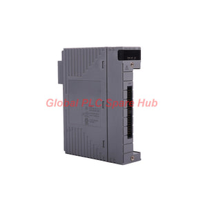
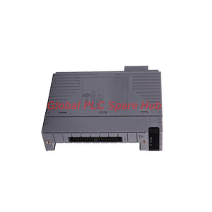
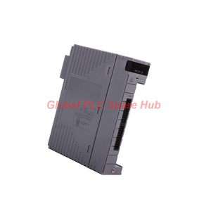
AAI143-S50/A4S00 Yokogawa Analog Input Module | 16-Channel Isolated
Manufacturer: Yokogawa
Product No.: AAI143-S50/A4S00
Condition: متوفر بالمخزون
Product Type: Analog Input Module
Product Origin: SG
Payment: T/T, Western Union
Weight: 350g
Shipping port: Xiamen
Warranty: 12 months
تقدير أوقات التسليم: 12-26 يومًا (دوليًا)، 3-6 أيام (الولايات المتحدة).
يجب الإرجاع خلال 30 يومًا من الشراء. الرسوم والضرائب غير قابلة للاسترداد.
دفع آمن ومضمون
AAI143-S50/A4S00 | Yokogawa Analog Input Module
The Yokogawa AAI143-S50/A4S00 is a 16-channel analog input module designed for industrial distributed control systems. It receives 4–20 mA analog signals from compatible field transmitters and transfers process measurements to the control system. This configuration combines the AAI143 isolated analog input module with an ATA4S-00 pressure-clamp terminal block. The terminal block supports organized field wiring and simplifies signal termination within compatible control cabinets. The specified configuration is a standard type without explosion protection. Engineers should verify the installed system, field signal requirements, terminal arrangement, and environmental conditions before ordering.
Technical Specifications
| Manufacturer | Yokogawa |
| Model | AAI143-S50/A4S00 |
| Series | AAI143 |
| Product Type | Analog Input Module |
| Input Signal | 4–20 mA DC |
| Number of Channels | 16 |
| Input Isolation | Isolated analog input design |
| Module Type | Standard type |
| Explosion Protection | Not included in this configuration |
| Basic Type Code | 0 |
| Terminal Block | Pressure-clamp terminal block |
| Terminal Block Model | ATA4S-00 |
| Optional Configuration | /A4S00 |
| Warranty | 12 months, subject to seller terms |
Detailed accuracy, input impedance, conversion resolution, sampling time, allowable overcurrent, and operating temperature are not specified in the supplied data. Consult the applicable Yokogawa documentation before using these values for engineering calculations.
Configuration Breakdown | Decode the Order Code
| Code Segment | Configuration Meaning |
| AAI143 | 16-channel isolated analog input module for 4–20 mA signals |
| S | Standard type |
| 5 | Configuration without explosion protection |
| 0 | Basic type |
| /A4S00 | Includes the specified pressure-clamp terminal block configuration |
| ATA4S-00 | Terminal block model associated with the optional code |
Selection note: The full designation AAI143-S50/A4S00 identifies both the input module configuration and its terminal interface. Verify the optional code when replacing an existing assembly.
Signal Acquisition and Functional Design
The module receives current signals from compatible field instruments. The control system then uses those values for process monitoring, alarms, operator displays, and control logic.
- Sixteen-channel integration: Consolidates multiple analog measurement points within a compatible control system configuration.
- 4–20 mA signal handling: Supports common industrial transmitter outputs for process variables.
- Input isolation: Helps separate the specified input circuitry according to the module design. Confirm the manufacturer's isolation ratings and wiring rules for the intended application.
- Pressure-clamp termination: Uses the ATA4S-00 terminal block configuration for field signal connections.
- Cabinet-level integration: Supports structured wiring and channel identification for maintenance and commissioning.
The module does not independently identify every field fault. Diagnostic results depend on the connected transmitter, system configuration, and available control system functions.
Typical Applications and Compatible Instruments
The AAI143-S50/A4S00 is suitable for compatible Yokogawa control installations that require 4–20 mA analog input acquisition.
- Pressure measurement: Receives current signals from compatible pressure transmitters.
- Temperature monitoring: Reads 4–20 mA outputs from temperature transmitters.
- Flow measurement: Integrates current outputs from compatible flow transmitters.
- Level monitoring: Acquires analog signals from supported level measurement instruments.
- Process equipment monitoring: Collects transmitter values for alarms, operator displays, and control sequences.
- Plant maintenance: Supports replacement projects that require the matching AAI143 configuration and terminal block.
Confirm the field instrument's output type and system compatibility before connection. A sensor that produces only a raw voltage, resistance, or thermocouple signal may require a suitable transmitter or interface.
Installation and Wiring Guide
1. Confirm the installed system Check the target Yokogawa system, module slot, hardware revision, and approved module configuration. Ensure the system supports the specified AAI143 variant. 2. Verify the terminal block Confirm the ATA4S-00 pressure-clamp terminal block and its mechanical interface. Check the required wiring accessories against the system documentation. 3. Identify each field signal Match the transmitter tag, channel number, polarity, and wiring schedule. Keep field conductors clearly identified to reduce cross-channel errors. 4. Check signal compatibility Verify that each transmitter provides a compatible 4–20 mA output. Confirm loop power requirements and wiring arrangements using the transmitter and system documentation. 5. Inspect wiring and termination Check conductor preparation, terminal seating, and cable routing. Follow the manufacturer's specified terminal procedures and grounding requirements. 6. Commission the input channels Verify channel configuration and compare the displayed value with an approved reference signal. Check representative channels before releasing the system for normal operation.
Diagnostics and Practical Troubleshooting
When an analog reading appears incorrect, check the complete signal loop before replacing the input module.
- Reading remains at zero: Verify loop power, transmitter operation, polarity, conductor continuity, and terminal assignments.
- Reading stays near the lower range: Check whether the transmitter is generating a valid current signal. Inspect loop resistance and wiring connections.
- Reading exceeds the expected range: Verify transmitter scaling, configured engineering units, input channel settings, and the measured loop current.
- Signal fluctuates: Inspect loose terminals, cable shielding, grounding, electromagnetic interference, and transmitter stability.
- Several channels fail together: Check shared field power, common wiring paths, terminal connections, and module status before isolating individual instruments.
- Fault appears after replacement: Confirm the model suffix, terminal block, channel mapping, and control system configuration.
Field example: A pressure transmitter displays an unexpectedly low process value. Measure the loop current using an approved method and compare it with the transmitter's expected output. If the current is correct, inspect channel scaling and terminal mapping. If the current is incorrect, investigate the transmitter, loop power, and field wiring first. Use approved procedures when measuring energized loops. Isolate circuits when required by the site safety procedure.
Compatibility and Purchasing Checklist
Before purchasing AAI143-S50/A4S00, verify the following:
- System support: Confirm that the target Yokogawa system accepts the AAI143 module variant.
- Signal type: Confirm that all connected instruments provide compatible 4–20 mA current outputs.
- Channel capacity: Check the 16-channel requirement against the actual application.
- Terminal interface: Verify the ATA4S-00 pressure-clamp terminal block and the required connection arrangement.
- Explosion protection: This configuration does not include explosion protection. Review site classification requirements before installation.
- Engineering data: Obtain the official accuracy, isolation, environmental, and electrical ratings required by the project.
Do not assume that modules sharing the AAI143 family name have identical terminal arrangements or suffix configurations. Match the complete order code to the existing system documentation.
Global PLC Spare HUB's Insight
The AAI143-S50/A4S00 should be selected as a module-and-terminal-block configuration. Confirming only the 4–20 mA signal type does not establish mechanical or system compatibility. During field replacement, engineers should record the original terminal assignments before disconnecting the wiring. After installation, verify each channel using a known reference current or a calibrated loop source where the approved procedure permits. This helps distinguish wiring errors from channel configuration problems. When several measurements drift together, investigate shared loop power, grounding, and interference before replacing multiple instruments. When one channel fails, check its transmitter and termination first. These steps create a more efficient fault-isolation process.
Packaging, Shipping, and Warranty
Configured product:
- Yokogawa AAI143-S50 analog input module.
- ATA4S-00 pressure-clamp terminal block, associated with the /A4S00 option.
- Additional cables and accessories only when listed in the sales quotation.
Confirm the delivered configuration and package contents before ordering. Warranty: 12 months, subject to the seller's written terms. Shipping methods: FedEx, UPS, and DHL. Dispatch target: 24–48 hours after order processing, subject to stock confirmation and shipping arrangements. Contact Global PLC Spare HUB for pricing, availability, terminal block confirmation, and technical compatibility checks.
Frequently Asked Questions
Q1: How can I check whether an analog input reading is caused by wiring or scaling? Compare the measured loop current with the expected transmitter output. If the current is correct, review channel scaling, engineering units, and channel assignment. If the current is incorrect, inspect the transmitter and field loop.
Q2: What should I verify when migrating existing field wiring to the ATA4S-00 terminal block? Confirm terminal numbering, signal polarity, conductor preparation, and channel mapping against the approved wiring diagram. Record the original connections before removal and test each channel after reconnection.
Q3: Can this module directly accept signals from a thermocouple or resistance temperature detector? The supplied specification identifies a 4–20 mA input module. Raw thermocouple and resistance signals require a compatible input interface or transmitter that converts the measurement into the supported current signal.
Q4: How should I investigate noise affecting multiple analog measurements? Check loop routing, cable shielding, grounding, shared power supplies, and nearby sources of electrical interference. Compare affected channels with unaffected channels to identify common wiring or installation issues.
Q5: What information should I provide when requesting a replacement quotation? Provide the complete model number, control system model, terminal block designation, required quantity, and field signal type. Include the installation environment and any specific accuracy or isolation requirements for compatibility review.

Tags
س: هل هذه الأجزاء أصلية وجديدة 100%؟
ج: نعم. نضمن أن كل مكون هو أصلي 100%، وجديد تمامًا، ومغلف من المصنع. كما نقدم ضمانًا شاملاً لمدة 12 شهرًا لراحتك.
س: ما مدى سرعة الشحن إلى بلدي؟
ج: بالنسبة للعناصر المتوفرة في المخزون، نقدم إرسالاً في نفس اليوم. وعادةً ما يتم التسليم عبر الشحن السريع الدولي (DHL/FedEx/UPS) في غضون 3-5 أيام عمل في جميع أنحاء العالم.
س: هل يمكنني الحصول على عرض أسعار رسمي يشمل تكاليف الشحن؟
ج: بالتأكيد. فريق المبيعات لدينا مستعد لتقديم فاتورة مبدئية (PI) مفصلة تتضمن أسعار الشحن الأكثر تنافسية لموقعك.
س: هل تقدمون خصومات للطلبات الكبيرة؟
ج: نقدم أسعارًا تعتمد على الحجم للمشاريع الكبيرة أو طلبات العناصر المتعددة. يرجى الاتصال بنا للحصول على ضمان أفضل الأسعار لدينا.
ضمان شامل لمدة 12 شهرًا
كل جزء توفره Global PLC Spare Hub مشمول بـ ضمان لمدة 12 شهرًا من تاريخ الفاتورة.
- التغطية: عيوب وظيفية وأعطال في الأجهزة في ظل ظروف التشغيل العادية.
- التزامنا: نقدم إصلاحًا فوريًا أو استبدالًا أو استردادًا كاملاً لأي مكونات معيبة تم التحقق منها لتقليل وقت التوقف التشغيلي لديك.
سياسة الإرجاع والاستبدال
نقدم سياسة إرجاع لمدة 30 يومًا لضمان حصولك على الجزء الدقيق الذي يتطلبه نظامك.
- الأهلية: تُقبل المرتجعات للعناصر غير المركبة في تغليفها الأصلي والمحكم الإغلاق من المصنع.
- عملية RMA: يرجى الاتصال بفريق الدعم لدينا للحصول على رقم ترخيص إرجاع البضائع (RMA) قبل الشحن.
- معالجة سريعة: تتم معالجة المبالغ المستردة أو الاستبدالات في غضون 3-5 أيام عمل بعد أن يجتاز العنصر المرتجع فحصنا الفني.
هل تحتاج إلى مساعدة فنية؟لست متأكدًا مما إذا كان هذا الجزء متوافقًا مع نظامك؟ [استشر مهندسينا] قبل الشراء لضمان التوافق بنسبة 100%.
اشترى الناس أيضًا


