


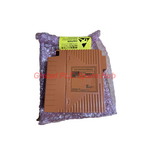
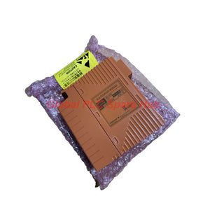
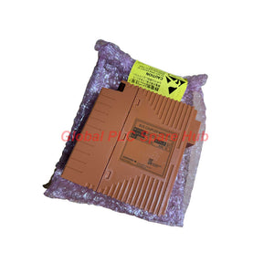
SEC402-51 Yokogawa ESB Bus Coupler Module Dual-Port Interface
Manufacturer: Yokogawa
Product No.: SEC402-51
Condition: In stock
Product Type: ESB Bus Coupler Module
Product Origin: SG
Payment: T/T, Western Union
Weight: 240g
Shipping port: Xiamen
Warranty: 12 months
Estimate delivery times: 12-26 days (International), 3-6 days (United States).
Return within 30 days of purchase. Duties & taxes are non-refundable.
Guaranteed Safe Checkout
Yokogawa SEC402-51 ESB Bus Coupler Module
The Yokogawa SEC402-51 is a two-port ESB Bus Coupler Module designed to provide the ESB bus master interface function in compatible Yokogawa safety control system configurations. It supports high-speed I/O data transmission between the safety control unit and connected ESB Bus Node Units, helping maintain an organized and reliable remote I/O architecture.
With a transmission speed of 128 Mbps and support for up to nine connectable units on each side, the SEC402-51 is intended for installations that require structured I/O expansion and communication across upper and lower ESB bus segments. Correct slot placement, cable length, node configuration, and suffix-code verification are essential for commissioning and long-term system availability.
1. Technical Specifications at a Glance
| Manufacturer | Yokogawa |
|---|---|
| Model | SEC402-51 |
| Product Series | SEC402 ESB Bus Coupler Module |
| Product Type | Two-Port ESB Bus Coupler Module |
| Primary Function | ESB bus master interface |
| Transmission Speed | 128 Mbps for I/O module data transmission |
| Connectable Units | Maximum 9 units on the upper side and 9 units on the lower side, subject to the applicable system configuration |
| Maximum Transmission Distance | 10 m for the upper ESB bus cable and 10 m for the lower ESB bus cable |
| Current Consumption | 0.5 A |
| Weight | Approximately 0.24 kg |
| Installation Position | Seventh and eighth slots of the specified safety control unit |
| Suffix Code -5 | Standard type without explosion protection |
| Suffix Code 1 | ISA Standard G3 environmental classification |
| Warranty | 12 months |
| Shipping Options | DHL, FedEx, and UPS |
2. Model Configuration Breakdown
The SEC402 ordering structure identifies the ESB bus coupler family and the applicable environmental and protection options.
SEC402 - 5 - 1
-
SEC402
- ESB Bus Coupler Module.
- Two-port interface configuration.
- Provides the ESB bus master interface function.
-
-5: Standard Type
- Standard version without explosion protection.
- Verify suitability for the actual installation area before ordering.
-
1: Environmental Specification
- ISA Standard G3 classification as specified in the ordering information.
- Relevant to installations where corrosive environmental contaminants may affect electronic equipment.
Ordering note: The complete ordering code should be confirmed against the nameplate and the applicable Yokogawa documentation. Do not infer explosion protection or other certifications from the ISA G3 suffix.
3. ESB Bus Architecture and Practical Value
The SEC402-51 serves as an ESB bus master interface within the supported safety control unit architecture. Its two-port configuration allows the system to connect upper and lower ESB bus segments, subject to the approved hardware arrangement.
| Architecture Element | Engineering Significance |
|---|---|
| Upper ESB bus | Provides a communication path for the connected upper-side ESB units within the permitted node count and cable length. |
| Lower ESB bus | Supports the corresponding lower-side ESB connections and helps organize I/O expansion. |
| 128 Mbps transmission | Defines the specified I/O data transmission rate. Actual system response also depends on controller execution, I/O configuration, and application requirements. |
| Maximum 9 units per side | Provides a planning limit for the documented configuration. The actual permissible topology must be checked against the hardware manual. |
| 10 m maximum per bus cable | Defines a physical installation constraint. Exceeding the specified distance may prevent reliable communication or cause node-related errors. |
For process plants, this architecture is useful when distributed safety I/O must be arranged around equipment groups, process areas, or cabinet layouts. The correct node arrangement can simplify wiring design and fault isolation, but it does not independently establish system redundancy or guarantee uninterrupted operation after a bus fault.
4. Compatible Equipment and Application Scenarios
- Yokogawa ProSafe-RS safety control systems: ESB bus interface applications using the compatible safety control unit and approved I/O node arrangement.
- Distributed safety I/O cabinets: Communication between the safety control unit and supported ESB Bus Node Units.
- Oil and gas facilities: Safety-system I/O architecture for process shutdown and related instrument interfaces, where the overall system design specifies compatible hardware.
- Chemical and petrochemical plants: Distributed I/O arrangements for safety instrumented applications.
- Industrial process facilities: Expansion or maintenance of supported safety control system configurations.
Compatibility warning: The SEC402-51 should not be treated as a general-purpose Ethernet switch or a universal CENTUM VP communication card. Verify the safety control unit model, slot allocation, ESB node type, cable specification, and engineering-system compatibility before installation.
5. Field Diagnostics and Troubleshooting Matrix
When ESB communication is unavailable or connected I/O nodes are not recognized, inspect the bus architecture and physical installation before concluding that the coupler itself has failed.
| Observed Symptom | Possible Cause | Recommended Diagnostic Action |
|---|---|---|
| Upper-side nodes are not recognized | Upper ESB cable fault, incorrect connection, node power issue, or configuration mismatch | Inspect the upper cable path, connectors, node power, and configured node list. |
| Lower-side nodes are not recognized | Lower ESB cable fault, incorrect connection, node power issue, or configuration mismatch | Check the lower bus independently and compare the detected nodes with the approved configuration. |
| Several nodes report communication errors | Shared bus connection problem, incorrect cable routing, power instability, or a configuration issue | Review system diagnostics and identify whether the affected nodes share the same bus segment. |
| Communication problems occur after maintenance | Partially seated module, disturbed connector, incorrect slot placement, or wiring changes | Review the maintenance record and verify module installation and cable connections under the approved procedure. |
| Fault persists after cable checks | Possible coupler hardware fault, node fault, or system configuration issue | Collect diagnostic codes, verify the supported configuration, and arrange a controlled hardware substitution test if permitted. |
6. Installation and Maintenance Recommendations
- Verify the designated slots. The supplied specification places the coupler in the seventh and eighth slots of the specified safety control unit. Confirm the applicable hardware manual and physical slot assignment before installation.
- Keep each ESB cable within its specified distance. Check upper and lower cable lengths separately. Inspect connectors and cable routing, especially after cabinet modifications or replacement work.
- Compare physical nodes with the approved configuration. Confirm that the upper and lower node counts, node types, and system configuration are supported. A communication error may originate in a connected node or configuration mismatch rather than the coupler itself.
- Preserve safety-system availability. Follow the approved maintenance procedure before removing a module or disconnecting an ESB cable. Do not perform uncontrolled disconnection tests on an operating safety system.
7. Global PLC Spare HUB Review
The Yokogawa SEC402-51 is a specialized two-port ESB Bus Coupler Module for compatible safety control system configurations. Its principal selection considerations are the upper and lower bus topology, permitted node count, cable distance, slot requirements, and environmental suffix.
For maintenance and procurement teams, confirming these details before replacement helps reduce commissioning delays and avoids confusing an ESB bus coupler with a general-purpose network interface. Actual compatibility must be established using the installed hardware configuration and the applicable manufacturer documentation.
8. Global PLC Spare HUB's Insight
Field engineering tip: If only one ESB segment loses communication, investigate that segment's cable, node power, and configuration before replacing the coupler. If both sides show faults at the same time, check shared hardware, system diagnostics, and recent maintenance changes first.
Record the affected node addresses or identifiers, diagnostic messages, upper and lower cable lengths, and the coupler's full ordering code. This information helps distinguish a segment-specific fault from a common system issue and makes replacement selection more accurate.
9. Warranty and Shipping
- Warranty: 12 months.
- Shipping methods: DHL, FedEx, and UPS.
- Before ordering: Confirm the complete model code, required environmental classification, slot compatibility, and ESB system configuration.
- Replacement support: Provide the existing part number and safety control unit model to help verify compatibility.
10. Frequently Asked Questions
Q1. What information should I collect before replacing an SEC402-51 that reports a bus communication fault?
Record the diagnostic messages, affected ESB segment, recognized node list, coupler model code, and any recent cabinet or wiring changes. This information helps establish whether the fault is localized to one cable segment or affects the wider configuration.
Q2. Can I use the SEC402-51 to increase the number of ESB nodes beyond the documented limit?
Do not exceed the documented maximum of nine units on either side without explicit support in the applicable Yokogawa system documentation. Verify the complete topology and the limitations of the installed safety control unit before planning an expansion.
Q3. Does the 128 Mbps transmission rate mean the safety application responds within a fixed time?
No. The transmission rate specifies the I/O data communication speed, not the complete safety function response time. Application execution, I/O processing, system configuration, and field-device response must also be considered when validating safety timing requirements.
Q4. What should I check if a replacement coupler powers up but some nodes remain unavailable?
Verify the upper and lower cable connections, cable lengths, connected node power, node configuration, and the installed coupler's compatibility. Compare the actual hardware arrangement with the approved configuration before concluding that the replacement module is defective.
Q5. How should I choose between standard and ISA G3 versions?
Select the environmental option according to the installation conditions and the manufacturer's ordering documentation. ISA G3 relates to environmental severity and corrosive contaminants; it does not itself establish explosion protection. Confirm any separate hazardous-area certification required by the installation.
Tags
Q: Are these parts 100% original and new?
A: Yes. Every component is guaranteed to be 100% original, brand-new, and factory-sealed. We also provide a 12-month comprehensive warranty for your peace of mind.
Q: How fast is the shipping to my country?
A: For in-stock items, we offer same-day dispatch. International express shipping (DHL/FedEx/UPS) typically delivers within 3–5 business days worldwide.
Q: Can I get a formal quotation with shipping costs?
A: Absolutely. Our sales team is ready to provide a detailed Proforma Invoice (PI) including the most competitive shipping rates for your location.
Q: Do you offer discounts for bulk orders?
A: We provide volume-based pricing for large projects or multiple-item orders. Please contact us to get our Best Price Guarantee.
12-Month Comprehensive Warranty
Every part supplied by Global PLC Spare Hub is covered by a 12-month warranty from the date of invoice.
- Coverage: Functional defects and hardware failures under normal operating conditions.
- Commitment: We provide immediate repair, replacement, or a full refund for any verified defective components to minimize your operational downtime.
Returns & Exchange Policy
We offer a 30-day return policy to ensure you receive the exact part your system requires.
- Eligibility: Returns are accepted for uninstalled items in their original, factory-sealed packaging.
- RMA Process: Please contact our support team to obtain a Return Merchandise Authorization (RMA) number before shipping.
- Fast Processing: Refunds or exchanges are processed within 3–5 business days after the returned item passes our technical inspection.
Need Technical Assistance?Not sure if this part is compatible with your system? [Consult our Engineers] before purchasing to ensure 100% compatibility.
People Also Bought


