


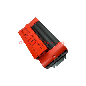
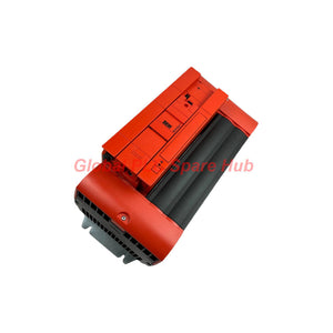
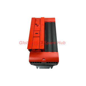
MC07B0550-5A3-4-00 SEW-Eurodrive Frequency Inverter | MOVITRAC B Control
Manufacturer: SEW-EURODRIVE
Product No.: MC07B0550-5A3-4-00
Condition: In stock
Product Type: Frequency Inverter
Product Origin: DE
Payment: T/T, Western Union
Weight: 10000g
Shipping port: Xiamen
Warranty: 12 months
Estimate delivery times: 12-26 days (International), 3-6 days (United States).
Return within 30 days of purchase. Duties & taxes are non-refundable.
Guaranteed Safe Checkout
SEW-Eurodrive MC07B0550-5A3-4-00 | MOVITRAC® 07B Frequency Inverter
The MC07B0550-5A3-4-00 is a high-power frequency inverter in the SEW-Eurodrive MOVITRAC® 07B range. It is specified for three-phase AC supply systems and motor applications rated at 55 kW. The drive provides V/f control for applications that require adjustable motor speed and controlled operation.
With digital and analog control interfaces, relay output, and RS-485 communication listed in the supplied specifications, this drive can support integration into industrial automation systems. Engineers should verify the exact electrical ratings, installed communication capabilities, and motor compatibility against the unit nameplate and applicable SEW documentation before commissioning.
01 | Ordering Code Architecture
| Code Segment | Identification | Configuration Notes |
|---|---|---|
| MC07B | Product family | MOVITRAC® 07B frequency inverter platform |
| 0550 | Model rating code | Associated with the specified 55 kW configuration; verify the exact rating in SEW documentation |
| 5A3 | Configuration code | Retain this code when matching a replacement. Confirm its detailed meaning using the official ordering-code documentation. |
| 4 | Configuration suffix | Preserve the exact code and verify its electrical or hardware significance with SEW documentation. |
| 00 | Final suffix | Preserve this suffix when matching the installed drive; confirm the option definition before substitution. |
Complete ordering code: MC07B0550-5A3-4-00
- Family: MOVITRAC® 07B
- Model code: 0550, specified for the 55 kW drive configuration
- Remaining suffixes: 5A3-4-00, which must match the required hardware and ordering configuration
The supplied information does not define every suffix position. Do not infer optional hardware, certification, or supply details from the suffix alone. Confirm the complete code against the original nameplate and the manufacturer's documentation before ordering a replacement.
02 | Electrical and Control Specifications
| Parameter | Specification |
|---|---|
| Manufacturer | SEW-Eurodrive |
| Part Number | MC07B0550-5A3-4-00 |
| Product Series | MOVITRAC® 07B / MOVITRAC® B |
| Product Type | Frequency inverter / variable-frequency drive |
| Specified Motor Power | 55 kW |
| Main Supply | Three-phase AC, specified as 3 × 380–500 V |
| Nominal Supply Reference | 400 V, three-phase |
| Rated Output / Line Current | 105 A, as supplied; confirm the exact current rating and whether it refers to input or output current |
| Separate Voltage Note | The supplied data also lists “AC 230 V” beside rated output current. This is a voltage value, not a current rating, and requires verification. |
| Control Mode | V/f control |
| Overload Capacity | 150% for 1 minute, subject to the manufacturer's operating conditions |
| Enclosure Protection | IP20 |
| Drive Size | Size 5 |
| Digital Inputs | 6 |
| Analog Inputs | 1 |
| Digital Outputs | 3 |
| Relay Outputs | 1 |
| Communication Interface | RS-485; Modbus RTU support listed in the supplied information. Confirm the required interface and configuration. |
| Approximate Weight | 10 kg |
Electrical selection warning: Confirm the drive's rated input and output currents separately. The supplied “105 A” rating and “AC 230 V” note are not sufficient to establish every operating limit. Use the manufacturer's rating tables and nameplate before selecting cables, protection devices, or a replacement drive.
03 | Drive Function and Control Interface
The MOVITRAC® 07B adjusts motor operation by controlling the electrical output supplied to a compatible AC motor. In V/f mode, the drive regulates the relationship between output voltage and frequency to support speed control.
- Speed adjustment: Change the commanded frequency to control motor speed within the configured operating limits.
- Digital command handling: Use supported digital inputs for control signals such as enable, start, or stop, subject to parameter assignment.
- Analog reference: Use the analog input for a compatible speed reference or process signal when configured for that purpose.
- Status signaling: Use digital and relay outputs for supported drive status or control functions.
- Automation integration: Verify the installed communication interface and configuration before connecting the drive to a supervisory system.
Terminal assignments and functions can depend on drive configuration and parameter settings. Confirm the correct terminal diagram and application manual before wiring control circuits.
04 | Typical Equipment and Application Scenarios
- Industrial pumps: Adjust motor speed to suit process demand, subject to the pump curve and minimum-flow requirements.
- Fans and ventilation systems: Support variable-speed operation where motor, airflow, and system pressure requirements permit.
- Conveyors: Provide adjustable motor speed for material handling and production-line coordination.
- Process machinery: Control compatible AC motors in mixing, material movement, and auxiliary process equipment.
- Production equipment: Integrate motor-speed commands and status signals into PLC-based control sequences.
- Drive replacement projects: Replace an installed MOVITRAC® unit after confirming motor ratings, supply voltage, control wiring, mounting, and parameter requirements.
Application suitability depends on the motor nameplate, required torque, load profile, acceleration and deceleration settings, and the drive's verified current rating. Do not select a drive on kilowatt rating alone.
05 | Installation and Commissioning Checklist
- Verify the nameplate: Confirm the complete part number, rated supply, output current, power rating, and hardware configuration.
- Check the motor: Compare motor voltage, current, frequency, power, and connection arrangement with the drive's output specifications.
- Review the supply: Confirm the incoming three-phase voltage is within the verified range for the exact drive variant.
- Plan protection and cabling: Size conductors and protective devices using manufacturer guidance and applicable electrical codes.
- Inspect the installation: Provide suitable ventilation, clearances, grounding, and enclosure protection. IP20 equipment requires protection appropriate to the installation environment.
- Configure control signals: Verify digital input assignments, analog reference scaling, output functions, and stop behavior.
- Set motor parameters: Enter the motor nameplate data and configure acceleration, deceleration, speed limits, and overload protection as required.
- Test at low risk: Conduct an initial run under controlled conditions. Confirm rotation direction, current draw, speed response, and stopping behavior.
- Record commissioning values: Save the parameter set, motor data, fault history, and final control configuration for maintenance.
Only qualified personnel should perform installation and commissioning. Isolate the supply and follow the manufacturer's discharge-time and electrical safety procedures before touching power terminals.
06 | Fault Diagnosis and Troubleshooting
| Observed Condition | Possible Cause | Recommended Checks |
|---|---|---|
| Drive does not start | Missing enable signal, incorrect input assignment, active fault, or unavailable supply | Check supply status, drive fault indication, digital input states, and start-command logic. |
| Motor runs but speed does not follow the command | Incorrect reference source, analog scaling, parameter settings, or control wiring | Verify the selected reference source, commanded frequency, analog input value, and active limits. |
| Drive trips during acceleration | Excessive load inertia, short acceleration time, current limit, or unsuitable motor configuration | Review fault history, motor data, acceleration settings, load condition, and verified drive current rating. |
| Motor overheats during operation | Excessive load, prolonged low-speed operation, incorrect motor parameters, or inadequate cooling | Measure motor current, check the load profile, verify parameter data, and assess motor cooling at low speed. |
| Communication is unavailable | Incorrect serial wiring, address or baud-rate mismatch, protocol configuration, or unsupported interface option | Confirm the installed interface, RS-485 wiring, communication settings, station address, and Modbus RTU configuration. |
| Drive operates intermittently | Loose terminals, supply disturbances, control interference, or unstable external commands | Inspect connections, monitor incoming supply conditions, review fault history, and check signal integrity. |
Diagnostic practice: Record the fault code and operating conditions before resetting the drive. Repeatedly resetting a trip without identifying its cause can hide developing motor, load, or electrical problems.
Global PLC Spare HUB's Insight
For a high-power inverter replacement, the most important checks are the actual current rating, the motor's electrical data, and the drive's control configuration. Two units with similar power ratings may not be interchangeable if their current capacity, hardware options, or interface arrangements differ.
Before removing an existing drive, save its parameter set and record the motor connection, command source, reference source, and fault history. After installation, verify motor rotation and low-speed response before testing the full load. If the new drive trips during acceleration, compare the recorded load profile and motor data before increasing ramp times or changing protection settings.
The listed RS-485 and Modbus RTU capabilities should also be confirmed on the actual unit. Check whether the intended communication function is supported by the installed hardware and firmware, and validate the register mapping before integrating the drive into a PLC or SCADA system.
Frequently Asked Questions
Q1: What information is most important when matching this inverter to a replacement motor?
Compare motor voltage, rated current, power, frequency, connection method, and required operating speed. Also consider starting torque, load inertia, duty cycle, and cooling. The verified drive output-current rating must support the motor under the intended operating conditions.
Q2: Should I copy the parameter set directly from the previous drive?
Use the existing parameter set as a reference, not as an automatic final configuration. Confirm that the replacement hardware supports the same functions and that motor data, terminal assignments, speed limits, and protection settings match the application. Test the new configuration under controlled conditions.
Q3: How should I investigate trips that occur only when the machine carries material?
Record the fault code, output current, speed command, and load condition during the trip. Compare these readings with unloaded operation. Check mechanical binding, process loading, acceleration settings, and the motor's rated current before changing protection parameters.
Q4: What should I verify before relying on Modbus RTU for remote control?
Confirm the drive's actual communication capability, the required interface hardware, serial wiring, baud rate, parity, station address, and supported registers. Test status and command handling separately, and retain a safe local stop method consistent with the machine's safety design.
Q5: Which details should I provide when requesting a quotation for this exact model?
Provide the full part number, nameplate photograph, motor power and rated current, supply voltage, application type, communication requirements, and any special mounting or environmental constraints. These details help verify the drive configuration and reduce the risk of ordering an incompatible unit.
Warranty, Shipping, and Package Details
- Product: SEW-Eurodrive MC07B0550-5A3-4-00 MOVITRAC® 07B frequency inverter
- Warranty: 12-month warranty, subject to the seller's applicable terms and conditions.
- Shipping methods: FedEx, UPS, and DHL, subject to destination and shipping arrangements.
- Package contents: One frequency inverter. Cables, braking components, communication accessories, and other items are included only when explicitly stated in the quotation.
- Compatibility support: Provide the full model number and application details for configuration review before ordering.
Request a quotation from Global PLC Spare HUB for the MC07B0550-5A3-4-00. Share your motor nameplate data and supply requirements to help confirm electrical compatibility before purchase.
Tags
Q: Are these parts 100% original and new?
A: Yes. Every component is guaranteed to be 100% original, brand-new, and factory-sealed. We also provide a 12-month comprehensive warranty for your peace of mind.
Q: How fast is the shipping to my country?
A: For in-stock items, we offer same-day dispatch. International express shipping (DHL/FedEx/UPS) typically delivers within 3–5 business days worldwide.
Q: Can I get a formal quotation with shipping costs?
A: Absolutely. Our sales team is ready to provide a detailed Proforma Invoice (PI) including the most competitive shipping rates for your location.
Q: Do you offer discounts for bulk orders?
A: We provide volume-based pricing for large projects or multiple-item orders. Please contact us to get our Best Price Guarantee.
12-Month Comprehensive Warranty
Every part supplied by Global PLC Spare Hub is covered by a 12-month warranty from the date of invoice.
- Coverage: Functional defects and hardware failures under normal operating conditions.
- Commitment: We provide immediate repair, replacement, or a full refund for any verified defective components to minimize your operational downtime.
Returns & Exchange Policy
We offer a 30-day return policy to ensure you receive the exact part your system requires.
- Eligibility: Returns are accepted for uninstalled items in their original, factory-sealed packaging.
- RMA Process: Please contact our support team to obtain a Return Merchandise Authorization (RMA) number before shipping.
- Fast Processing: Refunds or exchanges are processed within 3–5 business days after the returned item passes our technical inspection.
Need Technical Assistance?Not sure if this part is compatible with your system? [Consult our Engineers] before purchasing to ensure 100% compatibility.
People Also Bought


