


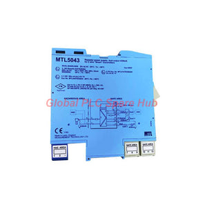
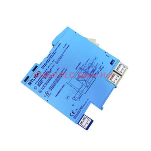
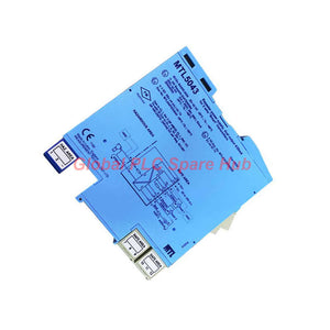
MTL5043 MTL HART Transmitter Interface Dual-Output
Manufacturer: MTL
Product No.: MTL5043
Condition: In stock
Product Type: Signal Repeater Isolator
Product Origin: EN
Payment: T/T, Western Union
Weight: 200g
Shipping port: Xiamen
Warranty: 12 months
Estimate delivery times: 12-26 days (International), 3-6 days (United States).
Return within 30 days of purchase. Duties & taxes are non-refundable.
Guaranteed Safe Checkout
MTL5043 Smart Transmitter Power Supply and Dual-Channel Signal Repeater
The MTL5043 is a single-channel transmitter interface designed for hazardous-area instrumentation. It supplies a conventional two-wire 4–20 mA smart transmitter and repeats its current signal through two electrically floating safe-area circuits.
Both outputs support independent safe-area loads. Channel 1 also supports bidirectional HART communication when the module carries the appropriate certification and hardware configuration.
The MTL5043 combines transmitter excitation, signal repetition, electrical isolation, and measurement-system integration in one interface. It helps engineers distribute a field measurement to two receiving devices without directly connecting their signal circuits.
01 | Signal Architecture and Operating Principle
The interface transfers a field measurement from a hazardous-area transmitter to two safe-area destinations. Each output operates within its specified load and current limits.
- Field transmitter supply: Provides 15.5 V at a 20 mA transmitter current.
- Primary output: Repeats the measured current to a safe-area instrument and supports HART communication in compatible versions.
- Secondary output: Provides a second current signal for another receiving device.
- Electrical isolation: Provides 250 V AC or DC isolation between the supply, input, and output circuits.
- Power status: A green LED indicates the presence of operating power.
Typical receiving devices include a PLC analog input, DCS input channel, panel meter, or process recorder. Confirm each device's input configuration and the selected output's electrical limits before connecting the circuits.
02 | Technical Data at a Glance
| Brand | MTL |
| Model | MTL5043 |
| Product Type | Smart transmitter power supply and dual-output current repeater |
| Channel Configuration | One transmitter input and two safe-area current outputs |
| Transmitter Type | Conventional two-wire 4–20 mA smart transmitter |
| Input Signal Range | 0–24 mA, including over-range |
| Output Signal Range | 4–20 mA nominal; 0–24 mA over-range capability under specified load conditions |
| Transmitter Voltage | 15.5 V at 20 mA |
| Transfer Accuracy | Better than 20 μA at 20°C; typically less than 5 μA |
| Temperature Drift | Less than 0.5 μA/°C |
| Response Time | Both outputs settle within 10% of the final value within 500 μs |
| Digital Signal Bandwidth | 400 Hz to 4 kHz |
| HART Communication | Supported through channel 1 on compatible versions |
| Safe-Area Output Resistance | Greater than 2 MΩ |
| Output Ripple | Less than 125 μA peak-to-peak |
| Supply Voltage | 20–35 V DC |
| Power Consumption | Maximum 100 mA at 24 V, 120 mA at 20 V, and 80 mA at 35 V, with two 20 mA signals |
| Power Dissipation | Maximum 1.7 W at 24 V, with two 20 mA signals |
| Electrical Isolation | 250 V AC or DC between supply, input, and outputs |
| Power Indicator | Green LED |
03 | Output Loading and Connection Options
Output loading determines whether the interface can drive the intended receiving equipment. Check the selected terminal arrangement before commissioning.
| Output Configuration | Specified Load Limit |
| Channel 1, terminals 11 and 12 | 0–350 Ω |
| Channel 1, terminals 10 and 11 | 0–130 Ω |
| Channel 2, active output | 0–550 Ω |
| Channel 2, passive current-sink output | Maximum 1 kΩ; maximum voltage 30 V |
| Over-range operation | 0–24 mA under the specified load conditions |
Engineering note: The source specification lists different load limits for channel 1 terminal arrangements. Verify the manufacturer's wiring diagram before selecting the HART connection or calculating the complete loop resistance.
04 | Terminal Assignment
| Terminal | Function |
| 1 | Input negative |
| 2 | Input positive |
| 7 | Channel 2 output negative, passive current sink |
| 8 | Channel 2 output negative, active configuration as specified |
| 9 | Channel 2 output positive, active configuration |
| 10 | Channel 1 output positive through a 220 Ω series resistor for HART applications |
| 11 | Channel 1 output negative |
| 12 | Channel 1 output positive |
| 13 | Supply negative |
| 14 | Supply positive |
Confirm the active or passive output arrangement against the exact module version. Never assume every certification variant provides identical terminal functions.
05 | Hazardous-Area Safety and Certification
The MTL5043 is specified for transmitter installations in Zone 0, IIC, T4–T6 hazardous areas when suitably certified. The source also lists Division 1, Group A hazardous locations.
- Safety output parameters: Uo = 28 V, Io = 93 mA, and Po = 0.65 W.
- Maximum external voltage: Um = 253 V RMS.
- Isolation rating: 250 V AC or DC between the power supply, input, and output circuits.
- Certification reference: Baseefa 03ATEX0584 identifies versions that support HART and comply with the stated specification.
- Variant warning: Versions marked BAS01ATEX7154 or Ex97D2248 do not support HART. The source also identifies differences in terminal 7 and the 220 Ω series resistor arrangement.
Check the complete certification marking and hardware configuration before ordering. Hazardous-area approval and HART functionality are version-dependent. Follow the applicable certificate, control drawings, and local installation regulations.
06 | Installation and Commissioning Workflow
- Identify the module: Check the model marking, certification reference, and HART requirements.
- Confirm the transmitter: Verify the two-wire 4–20 mA configuration and the required operating voltage.
- Calculate output loading: Include the receiving instrument, cable resistance, and any series components in the loop calculation.
- Choose output wiring: Select the active or passive channel 2 arrangement according to the receiving input.
- Connect the supply: Apply a suitable 20–35 V DC supply to terminals 13 and 14.
- Wire the signal circuits: Follow the approved terminal diagram and observe the specified polarity.
- Verify the power LED: Confirm the green indicator after energizing the module.
- Test both outputs: Apply a known process signal or use an approved loop calibrator to compare both receiving readings.
- Verify HART: On a compatible version, confirm digital communication through channel 1.
Isolate the relevant circuits and follow site safety procedures before changing wiring. Use approved equipment for hazardous-area testing.
07 | Field Diagnostics and Maintenance Insight
The MTL5043 helps engineers separate transmitter faults from signal distribution and receiving-device problems. Its dual outputs allow two measurement paths to receive the same field current.
- One output reads incorrectly: Compare both output currents and inspect the affected load, wiring, and receiving input.
- Both outputs show low readings: Check transmitter power, field-loop wiring, and input current before investigating the interface.
- HART communication fails: Confirm the module's certification marking, channel 1 wiring, loop resistance, and communicator connection.
- Readings fluctuate: Check loose terminals, grounding arrangements, cable routing, and interference sources.
- Unexpected over-range values: Compare the field current with the configured input range and receiving-device scaling.
Global PLC Spare HUB Review
For a practical commissioning example, consider a pressure transmitter that feeds both a DCS and a local recorder. If the DCS reading changes while the recorder remains stable, measure the two output currents independently. Then inspect the DCS input configuration, wiring resistance, and channel loading. This approach helps isolate a downstream fault without immediately replacing the field transmitter.
If both readings drift together, compare the field transmitter output with the interface outputs. Check the transmitter supply, calibration, and process conditions before concluding that the interface has failed.
The module supports signal-path diagnosis, but it does not independently identify sensor drift, process faults, or control-system scaling errors. Engineers must compare measurements with calibrated references and the actual process conditions.
08 | Compatible Equipment and Typical Applications
- Distributed Control Systems: Sends process measurements to a DCS while providing a second output for independent indication or recording.
- PLC analog input systems: Repeats a transmitter current to a compatible PLC input when the electrical loading requirements are satisfied.
- Pressure monitoring: Interfaces two-wire pressure transmitters used in process lines, utility systems, and plant instrumentation.
- Flow measurement: Distributes flow transmitter signals to control and monitoring equipment.
- Level control: Supplies a compatible level transmitter and provides separate current outputs for control and indication.
- HART instrument maintenance: Supports bidirectional HART communication through channel 1 on compatible hardware versions.
- Industrial process skids: Provides an interface for hazardous-area transmitters installed in packaged process equipment.
These applications require compatible transmitter characteristics and receiving inputs. The MTL5043 is not a universal replacement for every isolator, splitter, or HART interface.
09 | Selection Checklist for Replacement Projects
- Confirm the complete model number and certification marking.
- Determine whether the application requires HART communication.
- Verify the terminal 7 configuration and the presence of the 220 Ω series resistor.
- Check the transmitter's minimum operating voltage at the required loop current.
- Calculate the total load on each output circuit.
- Confirm whether the receiving equipment requires an active or passive current input.
- Review the hazardous-area documentation and control drawings.
- Confirm the supply voltage, installation requirements, and available documentation before purchase.
10 | Packaging, Shipping, and Warranty
| Product | MTL5043 smart transmitter power supply and dual-output current repeater |
| Packaging | Protective packaging; confirm included accessories and documents with the supplier |
| Dispatch Time | 24–48 hours, subject to stock confirmation and order processing |
| Shipping Methods | FedEx, UPS, and DHL |
| Warranty | 12 months, subject to the seller's written warranty terms |
| Quotation Support | Model verification, configuration checks, and delivery confirmation |
11 | Frequently Asked Questions
Q1: Why can two receiving instruments display different process values when they share one transmitter?
Answer: Different input scaling, wiring resistance, channel loading, or receiving-device faults can cause discrepancies. Compare the measured currents at both outputs before adjusting instrument scaling. Confirm that each load remains within its specified limit.
Q2: What should engineers consider when using the interface in a safety-related installation?
Answer: Verify the required hazardous-area approval and the complete loop's safety parameters. Check the applicable control drawings and system certification. Do not assume that an interface suitable for hazardous-area instrumentation automatically qualifies as a certified safety function.
Q3: Can a HART communicator access a transmitter through either output?
Answer: The supplied specification identifies HART repetition through channel 1 only. Use the approved channel 1 connection and confirm the module's certification marking. Do not assume that channel 2 passes HART signals.
Q4: How should engineers investigate an output that remains stable but disagrees with the process value?
Answer: Check the transmitter's calibration, process connection, configured range, and receiving-device scaling. Compare the measured current with a calibrated reference. A stable output does not prove that the original process measurement is correct.
Q5: Which MTL5043 version should buyers select for an existing HART instrument loop?
Answer: Confirm that the module carries the Baseefa 03ATEX0584 marking identified for HART-compatible operation in the supplied documentation. Check terminal 7 and the 220 Ω series resistor arrangement. Match the certification and wiring configuration to the existing control drawings before ordering.

Tags
Q: Are these parts 100% original and new?
A: Yes. Every component is guaranteed to be 100% original, brand-new, and factory-sealed. We also provide a 12-month comprehensive warranty for your peace of mind.
Q: How fast is the shipping to my country?
A: For in-stock items, we offer same-day dispatch. International express shipping (DHL/FedEx/UPS) typically delivers within 3–5 business days worldwide.
Q: Can I get a formal quotation with shipping costs?
A: Absolutely. Our sales team is ready to provide a detailed Proforma Invoice (PI) including the most competitive shipping rates for your location.
Q: Do you offer discounts for bulk orders?
A: We provide volume-based pricing for large projects or multiple-item orders. Please contact us to get our Best Price Guarantee.
12-Month Comprehensive Warranty
Every part supplied by Global PLC Spare Hub is covered by a 12-month warranty from the date of invoice.
- Coverage: Functional defects and hardware failures under normal operating conditions.
- Commitment: We provide immediate repair, replacement, or a full refund for any verified defective components to minimize your operational downtime.
Returns & Exchange Policy
We offer a 30-day return policy to ensure you receive the exact part your system requires.
- Eligibility: Returns are accepted for uninstalled items in their original, factory-sealed packaging.
- RMA Process: Please contact our support team to obtain a Return Merchandise Authorization (RMA) number before shipping.
- Fast Processing: Refunds or exchanges are processed within 3–5 business days after the returned item passes our technical inspection.
Need Technical Assistance?Not sure if this part is compatible with your system? [Consult our Engineers] before purchasing to ensure 100% compatibility.
People Also Bought


