


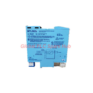

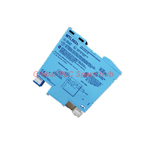
MTL5025 MTL Field Load Driver for Hazardous Areas
Manufacturer: MTL
Product No.: MTL5025
Condition: In stock
Product Type: Field Load Driver
Product Origin: EN
Payment: T/T, Western Union
Weight: 200g
Shipping port: Xiamen
Warranty: 12 months
Estimate delivery times: 12-26 days (International), 3-6 days (United States).
Return within 30 days of purchase. Duties & taxes are non-refundable.
Guaranteed Safe Checkout
MTL5025 | Intrinsically Safe On/Off Switching Interface
The MTL5025 is a single-channel switching interface for industrial control systems. It allows a safe-area switch or voltage change to control an on/off device in a hazardous area.
The interface drives certified intrinsically safe, low-power loads and non-energy-storing simple apparatus, including suitable LEDs. Its current-limited output supports switching applications that require controlled energy transfer into hazardous locations.
Within the MTL5000 series, the MTL5025 serves as a dedicated field-load control interface rather than an analog signal repeater. Engineers can use it to connect control commands with compatible field devices while maintaining the required intrinsic safety design.
01 | Control Function and Signal Path
The interface converts a safe-area switching command into an output suitable for a compatible hazardous-area load.
- Control input: A switch or voltage change in the safe area initiates the control action.
- Field output: The interface drives a compatible on/off device in the hazardous area.
- Output current limit: The hazardous-area output limits current to 45 mA.
- Load compatibility: The interface supports certified intrinsically safe low-power loads and suitable non-energy-storing simple apparatus.
- Status indication: A yellow LED provides status indication.
- Earth leakage monitoring: Terminal 3 provides the specified earth leakage detection connection.
Confirm the required control behavior and load characteristics before connecting the interface. The supplied specification does not define a universal input switching threshold or output response time.
02 | Core Technical Specifications
| Brand | MTL |
| Model | MTL5025 |
| Series | MTL5000 series |
| Product Type | Intrinsically safe on/off switching interface |
| Channel Count | One |
| Control Principle | Safe-area switch or voltage change controls a hazardous-area load |
| Minimum Output Voltage | 8.6 V at 45 mA |
| Maximum Output Voltage | 24 V from 269 Ω, as specified |
| Output Current Limit | 45 mA |
| Supply Voltage | 20–35 V DC |
| Maximum Current Consumption | 90 mA at 24 V with a 45 mA output; 110 mA across the stated 20–35 V DC supply range |
| Maximum Power Dissipation | 1.6 W at 24 V; 2.0 W at 35 V |
| Status Indicator | Yellow LED |
| Hazardous-Area Load | Suitable certified intrinsically safe low-power loads and compatible simple apparatus |
| Safety Parameters | 25 V, 269 Ω, 93 mA |
| Maximum External Voltage | Um = 250 V RMS or DC |
03 | Terminal Layout and Electrical Connections
| Terminal | Function |
| 1 | Hazardous-area output negative |
| 2 | Hazardous-area output positive |
| 3 | Earth leakage detection |
| 11 | Supply negative |
| 12 | Supply positive |
Wiring requirement: Follow the manufacturer's terminal diagram and approved installation drawings. Verify polarity, supply voltage, field-load requirements, and earth leakage detection wiring before energizing the circuit.
04 | Intrinsic Safety and Hazardous-Area Suitability
The MTL5025 is specified for loads in Zone 0, IIC, T4–T6 hazardous areas when suitably certified. The documentation also identifies Division 1, Group A hazardous locations.
- Output safety parameters: 25 V, 269 Ω, and 93 mA.
- External voltage rating: Um = 250 V RMS or DC.
- Load approval: Use a suitably certified intrinsically safe load or compatible simple apparatus.
- System verification: Check the interface and load parameters against the applicable intrinsic safety control drawing.
The supplied data does not include a specific certificate number or detailed installation conditions. Verify the product marking, approval documents, gas group, temperature class, and local regulatory requirements before installation.
05 | Installation and Commissioning Procedure
- Verify the model: Confirm the complete MTL5025 marking and the intended application.
- Check the field load: Verify the load's certification, operating voltage, current demand, and switching requirements.
- Review safety parameters: Confirm compatibility between the interface and the field device using approved control drawings.
- Check the supply: Verify that the DC supply remains within the specified 20–35 V range.
- Connect the field circuit: Wire terminals 1 and 2 according to the approved diagram.
- Connect the supply: Wire terminal 12 to supply positive and terminal 11 to supply negative.
- Inspect terminal 3: Confirm the required earth leakage detection arrangement for the installation.
- Apply the control command: Test the intended switching sequence under approved commissioning conditions.
- Verify the response: Check the yellow status LED and independently confirm the field device's actual state.
Isolate circuits before modifying connections. Use approved test methods and follow hazardous-area work procedures throughout commissioning.
06 | Field Diagnostics and Maintenance
The MTL5025 provides an interface between a control command and a hazardous-area switching load. Engineers can troubleshoot the control path by checking the supply, output circuit, field load, and actual device response separately.
- Load does not activate: Verify the supply voltage, command state, terminal polarity, field wiring, and load condition.
- Output voltage appears low: Compare the measurement with the specified output conditions and the connected load's current demand.
- Intermittent switching: Inspect terminal tightness, cable integrity, supply stability, and the field device's mechanical condition.
- Unexpected status indication: Compare the yellow LED with the control command and independently verify the output circuit.
- Earth leakage concern: Check the installation wiring and the designated terminal 3 arrangement using the approved procedure.
The yellow LED provides status information, but it does not independently prove that the field load has completed its mechanical action. Confirm the actual device state through suitable feedback or field inspection.
Global PLC Spare HUB's Insight
Field experience shows that an inactive hazardous-area load does not always indicate an interface failure. A wiring defect, unsuitable load, excessive current demand, or incorrect control configuration can produce similar symptoms.
Example: An operator commands a field-mounted solenoid valve to open, but the valve remains closed. First, verify the control command and the interface supply. Next, inspect the field wiring and compare the output measurements with the specified load conditions. Finally, test the solenoid and its mechanical mechanism using approved site procedures.
If the interface receives the correct command but the load does not respond, isolate the load and wiring before replacing the interface. If the supply or output measurements fall outside the specified conditions, investigate the associated circuit and load requirements.
This diagnostic sequence helps maintenance teams distinguish electrical interface faults from field-device problems. The MTL5025 does not independently diagnose valve position, actuator travel, or process conditions.
07 | Typical Applications and Compatible Equipment
- Solenoid valve control: Controls compatible low-power solenoid devices in hazardous-area process installations.
- Industrial on/off actuators: Interfaces suitable field loads with safe-area switching commands.
- Hazardous-area indicator circuits: Drives compatible LEDs and other approved non-energy-storing simple apparatus.
- PLC control systems: Connects a suitable PLC switching command to an approved field-load circuit.
- DCS output systems: Supports on/off commands from distributed control systems when the output interface and field load meet the required specifications.
- Process equipment packages: Supports discrete field-device control in compatible packaged instrumentation systems.
- Industrial interlocking systems: Can form part of an appropriately designed switching circuit, subject to the overall system's safety requirements.
Compatibility depends on the field load's electrical characteristics, certification, and installation requirements. Do not assume that every solenoid, relay, indicator, or PLC output is suitable for direct connection.
08 | Engineering Selection Checklist
- Confirm the hazardous-area classification and required equipment certification.
- Check the field load's rated voltage, current demand, and minimum operating requirements.
- Verify that the load is certified for the intended intrinsically safe circuit.
- Confirm the safe-area control signal and the required switching behavior.
- Check the 20–35 V DC supply requirement and available power capacity.
- Review the output safety parameters and the complete loop documentation.
- Confirm whether the application requires independent field-state feedback.
- Provide the complete model number and application details when requesting a quotation.
09 | Packaging, Shipping, and Warranty
| Product | MTL5025 intrinsically safe switching interface |
| Packaging | Protective packaging; confirm included accessories and documentation with the supplier |
| Dispatch Time | 24–48 hours, subject to stock confirmation and order processing |
| Shipping Methods | FedEx, UPS, and DHL |
| Warranty | 12 months, subject to the seller's written warranty terms |
| Quotation Support | Model verification, application checks, and delivery confirmation |
10 | Frequently Asked Questions
Q1: How should engineers assess whether the MTL5025 can drive a particular solenoid valve?
Answer: Check the valve's required operating voltage, current demand, and certification. Compare these values with the interface's output characteristics and approved intrinsic safety documentation. Confirm compatibility before connecting the load.
Q2: Why should technicians verify the actual load state instead of relying only on the yellow LED?
Answer: The LED provides status indication, but it does not necessarily confirm mechanical operation. A valve may remain stuck even when its electrical circuit responds. Use suitable feedback signals or an approved field inspection to confirm the final state.
Q3: What could cause repeated output failure after replacing a field device?
Answer: The replacement device may have different electrical requirements or certification parameters. Wiring errors and an unsuitable load can also cause problems. Compare the replacement specifications with the approved circuit design before restoring operation.
Q4: Can the MTL5025 replace a safety relay or safety PLC output?
Answer: Do not assume functional equivalence. The MTL5025 is an intrinsically safe switching interface, and the supplied information does not establish a safety integrity level. Select safety-related equipment according to the required safety function and certified system architecture.
Q5: What details help suppliers identify the correct replacement interface?
Answer: Provide the complete model marking, hazardous-area classification, field-device model, supply voltage, load current, and wiring diagram. Also identify any required approvals and installation constraints. These details help verify electrical suitability before ordering.

Tags
Q: Are these parts 100% original and new?
A: Yes. Every component is guaranteed to be 100% original, brand-new, and factory-sealed. We also provide a 12-month comprehensive warranty for your peace of mind.
Q: How fast is the shipping to my country?
A: For in-stock items, we offer same-day dispatch. International express shipping (DHL/FedEx/UPS) typically delivers within 3–5 business days worldwide.
Q: Can I get a formal quotation with shipping costs?
A: Absolutely. Our sales team is ready to provide a detailed Proforma Invoice (PI) including the most competitive shipping rates for your location.
Q: Do you offer discounts for bulk orders?
A: We provide volume-based pricing for large projects or multiple-item orders. Please contact us to get our Best Price Guarantee.
12-Month Comprehensive Warranty
Every part supplied by Global PLC Spare Hub is covered by a 12-month warranty from the date of invoice.
- Coverage: Functional defects and hardware failures under normal operating conditions.
- Commitment: We provide immediate repair, replacement, or a full refund for any verified defective components to minimize your operational downtime.
Returns & Exchange Policy
We offer a 30-day return policy to ensure you receive the exact part your system requires.
- Eligibility: Returns are accepted for uninstalled items in their original, factory-sealed packaging.
- RMA Process: Please contact our support team to obtain a Return Merchandise Authorization (RMA) number before shipping.
- Fast Processing: Refunds or exchanges are processed within 3–5 business days after the returned item passes our technical inspection.
Need Technical Assistance?Not sure if this part is compatible with your system? [Consult our Engineers] before purchasing to ensure 100% compatibility.
People Also Bought


