


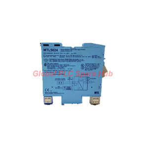
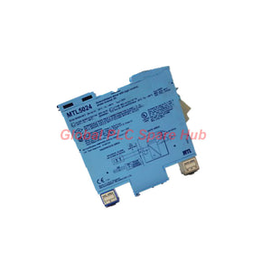

MTL5024 MTL5000 Series Solenoid Driver IS Alarm Control
Manufacturer: MTL
Product No.: MTL5024
Condition: In stock
Product Type: Switch Driver
Product Origin: EN
Payment: T/T, Western Union
Weight: 200g
Shipping port: Xiamen
Warranty: 12 months
Estimate delivery times: 12-26 days (International), 3-6 days (United States).
Return within 30 days of purchase. Duties & taxes are non-refundable.
Guaranteed Safe Checkout
MTL5024 Solenoid and Alarm Driver – Hazardous-Area Switching Interface
The MTL5024 is a single-channel, powered switching interface within the MTL5000 series. It controls hazardous-area on/off devices using a volt-free contact or logic signal from a safe-area controller. Unlike an analog output interface, this module operates as a discrete load driver. It supplies a current-limited output for compatible solenoids, alarms, LEDs, and other low-power field devices. A base-mounted phase reversal switch changes the relationship between the safe-area input and hazardous-area output. Engineers can select the required switching behavior without changing the controller's basic logic signal. The module supports suitable intrinsically safe loads and non-energy-storing simple apparatus. Its application requires verification of the field device's certification, electrical characteristics, and installation conditions.
At a Glance: Switching and Load Control
| Product | MTL5024 Solenoid/Alarm Driver |
| Series | MTL5000 |
| Channel Configuration | One switching channel |
| Control Input | Volt-free contact, open-collector transistor, or compatible logic signal |
| Field Output | Current-limited hazardous-area switching output |
| Output Current Limit | 45 mA |
| Output Voltage | Maximum 25 V; minimum 12.85 V at 45 mA |
| Supply | 20–35 V DC |
| Switching Configuration | Selectable normal or reversed phase |
| Indicators | Green power LED and yellow status LED |
Technical Specifications
| Manufacturer | MTL |
| Model Number | MTL5024 |
| Module Function | Solenoid and alarm driver |
| Number of Channels | 1 |
| Safe-Area Input | Switch contact, open-collector transistor, or logic drive |
| Input ON Threshold | Below 1.4 V, or closed contact, with normal phase selected |
| Input OFF Threshold | Above 4.5 V, or open contact, with normal phase selected |
| Reversed Phase Behavior | Inverts the stated input-to-output switching relationship |
| Minimum Output Voltage | 12.85 V at 45 mA |
| Maximum Output Voltage | 25 V |
| Output Current Limit | 45 mA |
| Supply Voltage | 20–35 V DC |
| Maximum Supply Current | 100 mA at 24 V; 120 mA at 20 V; 75 mA at 35 V |
| Typical Power Dissipation | 1.4 W with a typical solenoid, output ON |
| Worst-Case Power Dissipation | 2.0 W |
| Safety Parameters | Uo = 25 V; equivalent resistance = 170 Ω; Io = 147 mA |
| Maximum Working Voltage | Um = 250 V RMS or DC |
| Specified Hazardous-Area Application | Zone 0, IIC, T4–T6, subject to suitable certification |
| North American Classification | Division 1, Group A, subject to applicable approval |
The source specifications do not provide a full temperature range, switching frequency, response time, or ingress protection rating. Confirm these details against the applicable manufacturer's documentation.
Input Logic and Phase Selection
The MTL5024 accepts several safe-area control methods. Its phase switch determines whether the output follows or reverses the input state.
- Normal phase: A closed contact or input below 1.4 V turns the output ON.
- Normal phase: An open contact or input above 4.5 V turns the output OFF.
- Reverse phase: The output responds with the opposite state for the corresponding input condition.
- Logic interface: Compatible open-collector and logic signals can control the channel.
The supplied thresholds define clear ON and OFF conditions. Do not assume every voltage between 1.4 V and 4.5 V represents a guaranteed state. Check the manufacturer's complete input specification when designing the control circuit.
Terminal Layout and Wiring Reference
Use the following terminal assignments as a preliminary wiring reference. Confirm the physical terminal markings and manufacturer's wiring diagram before connecting equipment.
| Terminal | Function |
| 1 | Hazardous-area output negative |
| 2 | Hazardous-area output positive |
| 3 | Earth leakage detection connection |
| 11 | Safe-area control negative |
| 12 | Safe-area control positive |
| 13 | DC supply negative |
| 14 | DC supply positive |
Equipment and Applications
The module suits low-power discrete devices that meet its output and hazardous-area requirements.
Application boundary: The MTL5024 is a low-power driver. Do not assume it can directly operate high-current actuators, general-purpose lamps, or unverified inductive loads.
Installation and Commissioning Workflow
- Confirm the field load. Check its operating current, voltage, coil characteristics, and hazardous-area certification.
- Verify the supply. Maintain the specified 20–35 V DC supply range.
- Check the control signal. Confirm the controller provides a compatible contact or logic output.
- Select the phase. Set the base switch to match the intended control sequence.
- Review terminal wiring. Verify supply, input, output, and earth leakage detection connections.
- Test both states. Confirm that the field load switches ON and OFF as the controller commands.
- Check the indicators. Observe the green power LED and yellow status LED during functional tests.
- Record the results. Document the phase setting, field-device response, and measured operating values.
Isolate power before wiring or servicing. Follow site hazardous-area procedures and the manufacturer's installation instructions.
Field Diagnostics and Maintenance
The MTL5024 provides useful diagnostic checkpoints through its input logic, output behavior, current limit, and indicators. These checks help engineers narrow down field faults.
| Observed Condition | Recommended Investigation |
| Green power LED remains off | Measure the DC supply and inspect supply polarity and terminal connections. |
| Controller changes state, but the load does not | Verify the phase switch, input thresholds, field wiring, and load compatibility. |
| Output activates with the opposite command | Check whether reverse phase is selected and compare it with the control logic. |
| Solenoid operates intermittently | Measure supply stability and check the load's current demand against the 45 mA limit. |
| Output remains inactive despite valid input | Check the field circuit, terminal connections, load condition, and module status indication. |
| Field device behaves unexpectedly after replacement | Reconfirm coil specifications, certification, polarity, and the required switching phase. |
Global PLC Spare HUB Review A common commissioning issue occurs when a replacement driver uses a different phase setting from the original installation. The controller may issue the correct command, yet the field valve responds in reverse. For example, a normally de-energized process valve may energize when the controller output drops. Before changing PLC logic, check the MTL5024 phase switch and verify the intended safe state. Engineers should also distinguish a control fault from a load mismatch. A coil requiring more than the driver's current limit may fail to operate reliably. Confirm the device's actual electrical demand before replacing the interface.
Compatibility and Safe Selection
Choose the MTL5024 only after checking the complete control and field circuit.
- Control-system output: Verify contact, open-collector, or logic compatibility.
- Field-device demand: Confirm the required operating current does not exceed the 45 mA limit.
- Output voltage: Ensure the field load operates within the specified voltage capability.
- Switching logic: Confirm normal or reverse phase matches the intended sequence.
- Hazardous-area approval: Check the field device certification and installation conditions.
- System replacement: Compare terminal assignments, supply requirements, mounting arrangements, and applicable safety parameters.
The safety parameters listed here do not replace the full certification documents. Verify the approved entity parameters and conditions for the complete intrinsically safe circuit.
Warranty, Packaging, and Shipping
- Warranty: 12 months, subject to the seller's written warranty terms.
- Packaging: One MTL5024 module, subject to the confirmed order configuration.
- Shipping carriers: FedEx, UPS, and DHL, subject to destination and service availability.
- Order verification: Confirm model, quantity, stock status, and shipping arrangements before payment.
Contact Global PLC Spare HUB for a quotation, product availability, and assistance verifying application compatibility.
Frequently Asked Questions
Q1: How can engineers determine whether a solenoid is suitable for this driver? Check the coil's rated voltage, steady-state current, and operating requirements. Confirm that its demand fits the driver's current limit and output voltage. Also verify the coil's hazardous-area approval.
Q2: What should the phase switch setting represent in a shutdown application? It should match the required control sequence and defined safe state. Engineers must assess the entire shutdown circuit rather than choosing a phase based only on normal operating behavior.
Q3: Can a standard PLC transistor output control the MTL5024? The specification supports compatible open-collector and logic signals. Verify the PLC output voltage, polarity, and switching characteristics against the interface input requirements.
Q4: Why should engineers test the actual field load instead of relying only on an unloaded output measurement? A load can draw more current than the interface supports or require a different operating voltage. Testing under the intended load reveals problems that an unloaded voltage check may miss.
Q5: What information should buyers provide when choosing an equivalent driver? Provide the original part number, control-output type, field-load specifications, required phase behavior, supply voltage, terminal arrangement, and hazardous-area classification. These details support a safer compatibility assessment.

Tags
Q: Are these parts 100% original and new?
A: Yes. Every component is guaranteed to be 100% original, brand-new, and factory-sealed. We also provide a 12-month comprehensive warranty for your peace of mind.
Q: How fast is the shipping to my country?
A: For in-stock items, we offer same-day dispatch. International express shipping (DHL/FedEx/UPS) typically delivers within 3–5 business days worldwide.
Q: Can I get a formal quotation with shipping costs?
A: Absolutely. Our sales team is ready to provide a detailed Proforma Invoice (PI) including the most competitive shipping rates for your location.
Q: Do you offer discounts for bulk orders?
A: We provide volume-based pricing for large projects or multiple-item orders. Please contact us to get our Best Price Guarantee.
12-Month Comprehensive Warranty
Every part supplied by Global PLC Spare Hub is covered by a 12-month warranty from the date of invoice.
- Coverage: Functional defects and hardware failures under normal operating conditions.
- Commitment: We provide immediate repair, replacement, or a full refund for any verified defective components to minimize your operational downtime.
Returns & Exchange Policy
We offer a 30-day return policy to ensure you receive the exact part your system requires.
- Eligibility: Returns are accepted for uninstalled items in their original, factory-sealed packaging.
- RMA Process: Please contact our support team to obtain a Return Merchandise Authorization (RMA) number before shipping.
- Fast Processing: Refunds or exchanges are processed within 3–5 business days after the returned item passes our technical inspection.
Need Technical Assistance?Not sure if this part is compatible with your system? [Consult our Engineers] before purchasing to ensure 100% compatibility.
People Also Bought


