


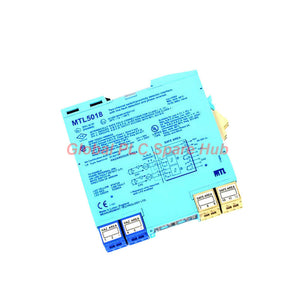
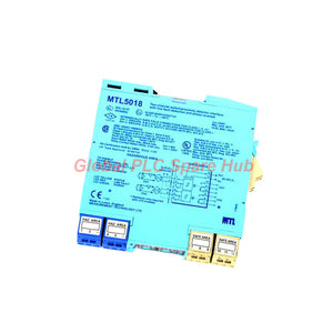
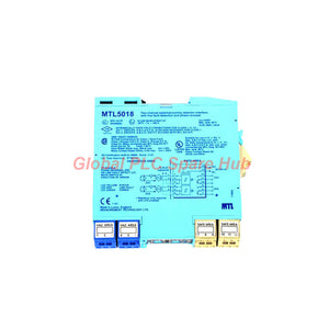
MTL5018 Dual-Channel Relay Interface | MTL5000 NAMUR Sensor Monitor
Manufacturer: MTL
Product No.: MTL5018
Condition: In stock
Product Type: Switch Amplifier
Product Origin: EN
Payment: T/T, Western Union
Weight: 200g
Shipping port: Xiamen
Warranty: 12 months
Estimate delivery times: 12-26 days (International), 3-6 days (United States).
Return within 30 days of purchase. Duties & taxes are non-refundable.
Guaranteed Safe Checkout
MTL5018 Dual-Channel NAMUR Switch Interface – Product Overview
The MTL5018 is a dual-channel switch interface from the MTL5000 series. It monitors two hazardous-area switches or proximity detectors and controls two independent safe-area relay outputs. The module accepts sensor signals that comply with NAMUR/DIN 19234 requirements. Each channel provides a changeover relay with independently selectable phase reversal. This configuration supports flexible alarm logic without requiring separate interface modules for each sensor. The selectable line fault detection (LFD) function identifies open and short circuits in either field circuit. When the module detects a line fault, the corresponding red LED illuminates and the affected relay de-energises.
01 | System Architecture and Signal Path
- Field input: Two hazardous-area switches or compatible NAMUR proximity detectors.
- Signal evaluation: Two independent channels evaluate sensor current or resistance.
- Logic configuration: Each channel supports independent phase reversal.
- Fault supervision: Selectable LFD monitors field wiring and provides channel-specific indications.
- Safe-area output: Two single-pole changeover relays transfer sensor states to control or alarm circuits.
This architecture suits applications that require two separate sensor signals and relay-based status transmission. Engineers can configure each channel for its own alarm condition and control requirement.
02 | Engineering Specification Card
| Manufacturer | MTL |
| Model | MTL5018 |
| Product Series | MTL5000 |
| Module Type | Dual-channel proximity switch interface and relay output module |
| Number of Channels | 2 |
| Input Standard | NAMUR / DIN 19234 |
| Sensor Supply | 7–9 V through 1 kΩ ±10% |
| Normal-Phase ON Condition | Input current greater than 2.1 mA or input resistance below 2 kΩ |
| Normal-Phase OFF Condition | Input current below 1.2 mA or input resistance above 10 kΩ |
| Typical Hysteresis | 200 µA |
| Relay Configuration | Two single-pole changeover relays |
| Maximum Relay Response Time | 10 ms |
| AC Contact Rating | 250 V AC, 2 A, cos φ greater than 0.7 |
| DC Contact Rating | 40 V DC, 2 A, resistive load |
| Supply Voltage | Refer to the applicable MTL5000 common specification and product documentation |
| Maximum Current Consumption | 60 mA at 20 V; 60 mA at 24 V; 40 mA at 35 V |
| Maximum Power Dissipation | 1.4 W at 24 V; 1.5 W at 35 V |
| Isolation | 250 V AC or DC between the supply, hazardous-area circuits, and relay outputs |
| Safety Parameters per Channel | 10.5 V, 800 Ω, 14 mA |
| Maximum Working Voltage | Um = 250 V RMS or DC |
| Power Indicator | Green LED |
| Channel Status Indicators | Two yellow LEDs; each illuminates when its relay output energises |
| Line Fault Indicators | Two red LEDs, one per channel |
03 | NAMUR Input Logic and Relay Operation
The module evaluates each input independently. Its normal and reversed phase settings determine how the sensor state controls the associated relay.
| Input Condition | Normal Phase | Reversed Phase |
| Current above 2.1 mA or resistance below 2 kΩ | Relay energised | Relay de-energised |
| Current below 1.2 mA or resistance above 10 kΩ | Relay de-energised | Relay energised |
The specified hysteresis is typically 200 µA. This helps prevent unstable switching when the sensor signal fluctuates near a switching threshold. Do not treat intermediate current or resistance values as guaranteed switching states. Check the manufacturer's complete input characteristics when evaluating borderline sensor signals.
04 | Line Fault Detection: Thresholds and Response
The selectable LFD function checks for wiring faults in each field circuit. Engineers can enable the function using the switches on the module's top surface.
| Fault Condition | Alarm Turns On | Alarm Turns Off | Relay Response |
| Open circuit | Input current below 100 µA | Input current above 250 µA | De-energises when a line fault is detected |
| Short circuit | Input resistance below 100 Ω | Input resistance above 360 Ω | De-energises when a line fault is detected |
When LFD operates with a contact input, install the specified resistors:
- Series resistor: 500 Ω to 1 kΩ in series with the switch.
- Parallel resistor: 20 kΩ to 25 kΩ across the switch.
These resistors allow the module to distinguish valid contact states from wiring faults. Follow the manufacturer's connection diagram when installing them.
05 | Terminal Assignment and Relay Connections
The following reference identifies the terminals for both sensor channels and relay outputs.
| Terminal | Function |
| 1 | Channel 1 input negative |
| 2 | Channel 1 input positive |
| 3 | Channel 1 earth leakage detection |
| 4 | Channel 2 input negative |
| 5 | Channel 2 input positive |
| 6 | Channel 2 earth leakage detection |
| 7 | Channel 2 normally-closed relay contact |
| 8 | Channel 2 relay common |
| 9 | Channel 2 normally-open relay contact |
| 10 | Channel 1 normally-closed relay contact |
| 11 | Channel 1 relay common |
| 12 | Channel 1 normally-open relay contact |
| 13 | Power supply negative |
| 14 | Power supply positive |
Reactive loads require adequate suppression. Select suppression components according to the load and the applicable circuit design. Confirm relay contact ratings before connecting external equipment.
06 | Where the MTL5018 Fits in a Control System
- Tank level monitoring: Interfaces two suitable proximity switches for independent high-level and low-level status signals.
- Conveyor monitoring: Monitors compatible position or proximity sensors and relays their states to safe-area control equipment.
- Valve position indication: Interfaces two suitable limit or proximity sensors for open and closed position feedback.
- Rotating equipment supervision: Transfers compatible discrete sensor states for position or presence monitoring.
- Process alarm systems: Provides separate relay outputs for sensor-based alarms and interlock inputs.
- Oil, gas, and chemical facilities: Interfaces appropriately certified field sensors installed in classified hazardous locations.
The module provides signal interfacing and relay switching. It does not independently establish a safety integrity level or replace the risk assessment for a safety-related control system.
07 | Commissioning Workflow for Field Engineers
Step 1 — Verify sensor compatibility Confirm that both field sensors meet the required NAMUR/DIN 19234 characteristics. Check their certifications and wiring requirements before installation. Step 2 — Confirm the channel configuration Identify which sensor connects to Channel 1 and which connects to Channel 2. Record the required phase setting for each channel. Step 3 — Configure line fault detection Select LFD according to the application requirements. For contact inputs, install the specified series and parallel resistors. Step 4 — Test switching thresholds Apply valid sensor states and verify that each relay changes state at the expected current or resistance levels. Step 5 — Test fault response Where the approved test procedure permits, simulate open- and short-circuit conditions. Confirm the relevant red LED illuminates and the relay de-energises. Step 6 — Verify output contacts Use a suitable meter to confirm the common, normally-open, and normally-closed contact behavior for both channels. Step 7 — Record the final settings Document phase selection, LFD configuration, relay response, and sensor identification. This record helps future maintenance teams diagnose changes more quickly.
08 | Global PLC Spare HUB Review
In dual-sensor installations, an incorrect phase setting can create confusing relay behavior even when both sensors operate correctly. Engineers should verify each channel separately before investigating the controller program. For example, a valve assembly may use one sensor for the open position and another for the closed position. If Channel 2 uses the wrong phase, its relay may energise at the wrong sensor state. Check the phase switch and confirm the actual relay contacts before changing PLC logic. A second practical concern involves line fault detection on mechanical contacts. Without the specified resistor network, the module may not distinguish normal contact states from wiring faults reliably. Confirm the LFD configuration during commissioning rather than treating it as a software-only setting. These checks help isolate sensor, wiring, configuration, and relay-contact problems. They also reduce unnecessary replacement of functioning interface modules.
09 | Troubleshooting Reference
- Red LFD LED remains on: Inspect the sensor cable, terminal connections, and resistor network. Measure the input current or resistance using the approved procedure.
- Yellow channel LED does not follow the sensor: Check the sensor signal against the specified thresholds and verify the phase setting.
- Relay status is correct but the external circuit fails: Test the relay contacts, external supply, wiring, and connected load.
- False alarms occur during contact switching: Check the LFD resistor values and wiring arrangement. Review the sensor's actual electrical characteristics.
- One channel works while the other fails: Compare the channel wiring, phase selection, sensor condition, and relay contact continuity.
- Relay contacts fail under inductive loads: Check load current and voltage, and verify adequate suppression for the reactive load.
Always isolate circuits before resistance measurements or wiring changes. Do not bypass hazardous-area protection or approved fault monitoring to restore operation.
10 | Hazardous-Area Compatibility and Selection
The supplied specification identifies these intended field-location classifications:
- Switch applications: Zone 0, IIC, T6, and Division 1, Group A, subject to applicable certification.
- Proximity detector applications: Zone 0, IIC, T4–T6, when suitably certified, and Division 1, Group A, subject to applicable approval.
- Isolation: 250 V AC or DC between the power supply, hazardous-area circuits, and relay outputs.
- Safety parameters per channel: 10.5 V, 800 Ω, and 14 mA.
Verify the exact certificate, sensor approval, installation conditions, and applicable entity parameters before use. These specification values alone do not establish certification for every installation. When selecting a replacement, compare channel count, input standard, relay contact arrangement, LFD requirements, phase selection, terminal layout, and isolation. A two-channel relay interface is not automatically interchangeable with a single-channel switching module.
11 | Frequently Asked Questions
Q1: Can both channels monitor different types of sensors? Each channel operates independently, but both inputs must satisfy the applicable electrical requirements. Confirm compatibility for each sensor type and the intended wiring configuration before mixing devices.
Q2: How should engineers choose between normally-open and normally-closed relay contacts? Select contacts according to the external circuit's required de-energised state and alarm philosophy. Verify actual contact behavior during commissioning rather than relying on the sensor's name or PLC tag.
Q3: What should maintenance teams record when investigating intermittent line fault alarms? Record the affected channel, measured current or resistance, LED state, sensor condition, cable condition, and LFD resistor values. Compare readings under normal and fault conditions to identify recurring wiring problems.
Q4: Does the 10 ms relay response time represent the complete system response? No. It specifies the relay response, not the complete sensor-to-controller response. Sensor delay, input evaluation, external wiring, and downstream controller processing may add further delay.
Q5: What details help confirm the correct replacement for an existing installation? Provide the full model number, sensor type, channel assignments, required relay contact logic, LFD configuration, supply details, and hazardous-area classification. Include terminal photographs or the existing wiring diagram when available.
12 | Packaging, Warranty, and Shipping
- Product: MTL5018 dual-channel switch interface module.
- Package contents: One module, subject to the confirmed order configuration.
- Warranty: 12 months, subject to the seller's written warranty terms.
- Shipping options: FedEx, UPS, and DHL, subject to destination and service availability.
- Order verification: Confirm model, stock availability, quantity, and shipping arrangements before purchase.
Contact Global PLC Spare HUB for a quotation, product availability, and assistance checking the module against your sensor and relay requirements.

Tags
Q: Are these parts 100% original and new?
A: Yes. Every component is guaranteed to be 100% original, brand-new, and factory-sealed. We also provide a 12-month comprehensive warranty for your peace of mind.
Q: How fast is the shipping to my country?
A: For in-stock items, we offer same-day dispatch. International express shipping (DHL/FedEx/UPS) typically delivers within 3–5 business days worldwide.
Q: Can I get a formal quotation with shipping costs?
A: Absolutely. Our sales team is ready to provide a detailed Proforma Invoice (PI) including the most competitive shipping rates for your location.
Q: Do you offer discounts for bulk orders?
A: We provide volume-based pricing for large projects or multiple-item orders. Please contact us to get our Best Price Guarantee.
12-Month Comprehensive Warranty
Every part supplied by Global PLC Spare Hub is covered by a 12-month warranty from the date of invoice.
- Coverage: Functional defects and hardware failures under normal operating conditions.
- Commitment: We provide immediate repair, replacement, or a full refund for any verified defective components to minimize your operational downtime.
Returns & Exchange Policy
We offer a 30-day return policy to ensure you receive the exact part your system requires.
- Eligibility: Returns are accepted for uninstalled items in their original, factory-sealed packaging.
- RMA Process: Please contact our support team to obtain a Return Merchandise Authorization (RMA) number before shipping.
- Fast Processing: Refunds or exchanges are processed within 3–5 business days after the returned item passes our technical inspection.
Need Technical Assistance?Not sure if this part is compatible with your system? [Consult our Engineers] before purchasing to ensure 100% compatibility.
People Also Bought


