


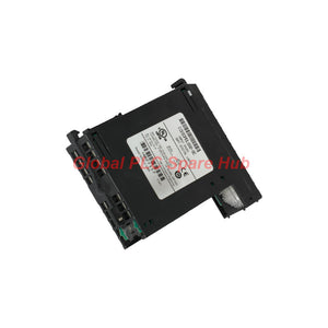
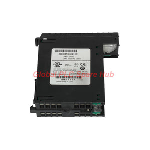
IC693MDL660 GE Fanuc 90-30 Discrete Input Module 24VDC Logic
Manufacturer: GE Fanuc
Product No.: IC693MDL660
Condition: In stock
Product Type: Discrete Input Module
Product Origin: USA
Payment: T/T, Western Union
Weight: 990g
Shipping port: Xiamen
Warranty: 12 months
Estimate delivery times: 12-26 days (International), 3-6 days (United States).
Return within 30 days of purchase. Duties & taxes are non-refundable.
Guaranteed Safe Checkout
GE Fanuc IC693MDL660 | 32-Point DC Digital Input Module
The IC693MDL660 is a 32-point discrete input module for the GE Fanuc Series 90-30 PLC platform. It monitors DC signals from field devices and transfers their logical states to the PLC controller.
Its four input groups support eight channels each. The module accepts nominal 24 VDC signals and supports positive or negative logic wiring. This configuration helps engineers integrate switches, proximity sensors, pushbuttons, and other discrete field devices into industrial control systems.
The GE Fanuc IC693MDL660 is a single-slot module designed for compatible Series 90-30 baseplates. It provides individual input status LEDs for convenient commissioning and fault isolation.
01 | Engineering Overview
- 32 discrete input points: Monitors multiple field signals through one PLC module.
- Four isolated input groups: Organizes 32 channels into four groups of eight.
- 24 VDC nominal input: Supports common industrial DC control signals.
- Positive and negative logic: Supports different field wiring arrangements.
- Individual status indicators: Green LEDs show input states for channel-level troubleshooting.
- Single-slot installation: Fits compatible Series 90-30 baseplates.
- Terminal block options: Supports the specified IC694TBB032 box-style and IC694TBS032 spring-clamp terminal blocks.
02 | Technical Specifications
| Brand | GE Fanuc |
| Manufacturer Information | GE Fanuc; the product line is associated with Emerson Automation following corporate changes. |
| Series | Series 90-30 |
| Model / Part Number | IC693MDL660 |
| Module Type | 32-point discrete DC input module |
| Number of Channels | 32 inputs |
| Input Grouping | 4 groups, 8 channels per group |
| Nominal Input Voltage | 24 VDC |
| Specified Input Voltage Range | 0–30 VDC; verify operating thresholds against the official hardware manual. |
| Rated Voltage Tolerance | +10% / −20% around 24 VDC, as stated in the supplied information. |
| Typical Input Current | Approximately 7 mA at rated voltage; another supplied specification lists 7.5 mA. |
| Minimum ON-State Voltage | 15 VDC listed in the supplied specifications; confirm the exact threshold in the hardware manual. |
| OFF-State Voltage | 6 VDC listed in the supplied specifications. |
| ON-State Current | 4.5 mA listed in the supplied specifications; verify the applicable threshold. |
| Maximum OFF-State Current | 2 mA listed in the supplied specifications. |
| Field-to-Logic Isolation | 1500 V stated; verify the rating and test conditions in official documentation. |
| Maximum ON Response Time | Conflicting values appear in the supplied data. Verify the official specification before use. |
| Maximum OFF Response Time | Conflicting values appear in the supplied data. Verify the official specification before use. |
| Wiring Logic | Positive or negative logic |
| Module Width / Slot Requirement | Single slot |
| Compatible Baseplates | Series 90-30 5-slot or 10-slot baseplates, subject to system configuration. |
| Terminal Block Options | IC694TBB032 box-style or IC694TBS032 spring-clamp style, as specified. |
| Internal Power Consumption | Verify the required 5 VDC backplane current in the official hardware manual. |
| Operating Temperature | Confirm the permitted temperature range in the applicable hardware manual. |
03 | How the 32 Input Channels Work
The IC693MDL660 monitors field voltage states and presents corresponding digital states to the PLC. Each group contains eight input channels.
- Group 1: Eight discrete input points.
- Group 2: Eight discrete input points.
- Group 3: Eight discrete input points.
- Group 4: Eight discrete input points.
This grouping helps organize field wiring and simplifies signal tracing. Check the module wiring diagram for group commons and permitted circuit arrangements before connecting field power.
04 | Positive and Negative Logic Wiring
The module supports both positive and negative logic configurations. The correct arrangement depends on the field supply polarity, common connections, and input device design.
| Wiring Method | General Principle | Engineering Check |
| Positive logic | A positive field voltage establishes the ON state relative to the designated common. | Verify the negative common connection and input polarity. |
| Negative logic | The circuit uses the opposite reference arrangement to establish the ON state. | Verify the positive common connection and device switching path. |
Do not select a wiring method from terminology alone. Follow the official group wiring diagram and confirm the electrical behavior of the connected sensors or switches.
05 | Field Devices and Compatible Equipment
This module is intended for discrete DC signal acquisition. It does not replace an analog input module for continuous voltage, current, temperature, or pressure measurements.
- Proximity sensors: Suitable DC switching sensors that meet the input electrical requirements.
- Limit switches: Mechanical position feedback for actuators, conveyors, and machine guards.
- Pushbuttons and selector switches: Operator commands and equipment status signals.
- Auxiliary contacts: Feedback from contactors and relays when the contact circuit meets the input requirements.
- Machine status signals: Discrete running, stopped, ready, and fault indications.
- Series 90-30 PLC systems: Compatible baseplates and controller configurations with available I/O capacity.
Check sensor output type, ON-state voltage, OFF-state leakage, common wiring, and input thresholds before connecting a device. Electronic sensors may behave differently from dry-contact switches.
06 | Installation and Wiring Checklist
- Confirm the part number: Check that the module label reads IC693MDL660.
- Check the PLC platform: Confirm the Series 90-30 baseplate and available I/O slot.
- Verify the terminal block: Confirm compatibility with the installed terminal block and field wiring arrangement.
- Isolate the equipment: Follow site lockout and electrical safety procedures before installation.
- Identify input groups: Map each field device to the correct channel and group common.
- Confirm logic polarity: Select positive or negative logic according to the wiring design.
- Inspect field wiring: Check polarity, continuity, insulation, and terminal tightness.
- Test each point: Operate field devices and compare physical states with LED indications and PLC input data.
Use the manufacturer's wiring diagram and installation instructions. Do not insert or remove modules under power unless the hardware documentation explicitly permits that procedure.
07 | LED Diagnostics and Fault Isolation
Individual input status LEDs provide a quick indication of field signal states. They help technicians narrow down faults before investigating the controller program or replacing hardware.
| Observed Condition | Possible Cause | Recommended Action |
| LED remains off when a sensor operates | Missing field voltage, incorrect polarity, open wiring, or an unsuitable signal level. | Measure the input voltage and inspect the sensor circuit. |
| LED remains on when a sensor is inactive | Unexpected voltage, wiring cross-connection, or a device that does not switch fully off. | Check the inactive-state voltage and sensor leakage current. |
| LED state differs from the PLC program | Incorrect address mapping, logic inversion, or configuration error. | Compare the physical channel, PLC reference address, and program logic. |
| Several inputs fail together | Group common wiring, shared supply, or terminal connection problem. | Inspect the affected group's common and field power distribution. |
| Input changes appear delayed | Input filtering, module response characteristics, program scan time, or communication delays. | Check the complete signal path and official module timing specification. |
08 | Global PLC Spare HUB's Insight
When several inputs fail simultaneously, inspect shared wiring before replacing the module. The four-group architecture makes common connections an important troubleshooting point.
Field example: Eight proximity sensor signals disappear from a packaging machine after maintenance. The affected input LEDs remain off, while the other three groups continue operating.
- Measure the field supply at an affected sensor.
- Check the wiring and common connection for the affected eight-channel group.
- Measure the voltage at the module input terminals while operating a sensor.
- Compare the LED state with the PLC input reference and program logic.
- Test an individual channel using an approved procedure before considering module replacement.
If all eight channels share the same fault, a group common or shared supply problem deserves early attention. This approach can reduce unnecessary module changes and shorten downtime.
09 | Selection and Replacement Considerations
Choose the IC693MDL660 according to the electrical interface and physical requirements of the existing Series 90-30 installation.
- Channel count: Confirm that 32 discrete inputs meet the required point count.
- Signal voltage: Verify compatibility with the field device's ON and OFF voltage levels.
- Logic polarity: Match the existing positive or negative logic wiring.
- Group arrangement: Check commons and field power distribution for all four groups.
- Mechanical fit: Verify the single-slot requirement and terminal block compatibility.
- Response time: Confirm the official switching specification if the application uses fast signals.
- System capacity: Check baseplate slots, controller I/O limits, and available configuration memory.
Do not substitute another Series 90-30 input module based only on its nominal 24 VDC rating. Channel count, thresholds, isolation, wiring, and timing may differ.
10 | Typical Industrial Applications
- Packaging lines: Read photoelectric sensors, limit switches, and machine status contacts.
- Conveyor systems: Monitor product presence, transfer positions, and drive auxiliary contacts.
- Water treatment: Acquire discrete equipment status and switch feedback signals.
- Material handling: Monitor position switches and operating states across machine sections.
- General manufacturing: Collect pushbutton commands and interlock feedback for PLC logic.
- Machine retrofits: Maintain compatible discrete signal interfaces within existing Series 90-30 control systems.
11 | Packaging, Warranty, and Shipping
- Product: GE Fanuc Series 90-30 IC693MDL660 discrete input module.
- Packaging: Protective packaging suitable for international transport.
- Included accessories: Terminal blocks, cables, and additional documents are included only when specified in the quotation.
- Warranty: 12 months under the agreed sales terms.
- Pre-shipment checks: Model identification and available inspection checks can be confirmed before dispatch.
- Dispatch target: Typically 24–48 hours after order confirmation, subject to stock and payment verification.
- Courier options: FedEx, UPS, and DHL.
- Quotation support: Contact Global PLC Spare HUB for availability, pricing, and delivery estimates.
12 | Frequently Asked Questions
Q1: How should I plan input allocation across the four groups?
Map the 32 field signals by machine section, function, and common connection. Keep the channel schedule consistent with the wiring drawings and PLC address list. This simplifies commissioning and future maintenance.
Q2: Can a two-wire electronic sensor replace a mechanical switch on this module?
Only if its output behavior matches the module's input requirements. Check the sensor's switching polarity, minimum ON current, OFF-state leakage, and voltage drop before connecting it.
Q3: What should I check when the input LED is on but the machine sequence does not advance?
Confirm the PLC input reference, program conditions, interlocks, and sequence state. An illuminated channel LED indicates an input state, but it does not prove that every program condition is satisfied.
Q4: How can I confirm that the existing terminal block is suitable for a replacement module?
Read the terminal block part number and compare it with the module's approved accessories. Also check wiring condition, terminal labeling, conductor size, and the existing group's common arrangement.
Q5: What information should I send when requesting a quotation for an installed system?
Provide the complete part number, installed baseplate type, terminal block model, field signal voltage, required quantity, and destination country. Photos of the module label and wiring layout can help verify the configuration.
Request a Quote for IC693MDL660
Looking for the IC693MDL660 32-point DC input module for Series 90-30 maintenance or system integration?
Contact Global PLC Spare HUB for pricing, availability, terminal block compatibility checks, and international shipping through FedEx, UPS, or DHL.
Tags
Q: Are these parts 100% original and new?
A: Yes. Every component is guaranteed to be 100% original, brand-new, and factory-sealed. We also provide a 12-month comprehensive warranty for your peace of mind.
Q: How fast is the shipping to my country?
A: For in-stock items, we offer same-day dispatch. International express shipping (DHL/FedEx/UPS) typically delivers within 3–5 business days worldwide.
Q: Can I get a formal quotation with shipping costs?
A: Absolutely. Our sales team is ready to provide a detailed Proforma Invoice (PI) including the most competitive shipping rates for your location.
Q: Do you offer discounts for bulk orders?
A: We provide volume-based pricing for large projects or multiple-item orders. Please contact us to get our Best Price Guarantee.
12-Month Comprehensive Warranty
Every part supplied by Global PLC Spare Hub is covered by a 12-month warranty from the date of invoice.
- Coverage: Functional defects and hardware failures under normal operating conditions.
- Commitment: We provide immediate repair, replacement, or a full refund for any verified defective components to minimize your operational downtime.
Returns & Exchange Policy
We offer a 30-day return policy to ensure you receive the exact part your system requires.
- Eligibility: Returns are accepted for uninstalled items in their original, factory-sealed packaging.
- RMA Process: Please contact our support team to obtain a Return Merchandise Authorization (RMA) number before shipping.
- Fast Processing: Refunds or exchanges are processed within 3–5 business days after the returned item passes our technical inspection.
Need Technical Assistance?Not sure if this part is compatible with your system? [Consult our Engineers] before purchasing to ensure 100% compatibility.
People Also Bought


