


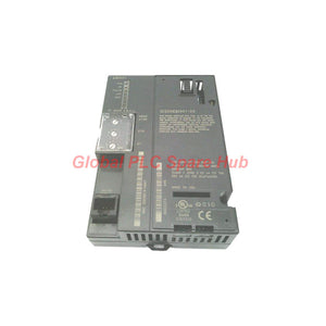
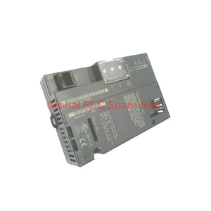

IC200ERM001 GE Fanuc VersaMax Expansion Module In Stock
Manufacturer: GE Fanuc
Product No.: IC200ERM001
Condition: In stock
Product Type: Expansion Receiver Module
Product Origin: USA
Payment: T/T, Western Union
Weight: 200g
Shipping port: Xiamen
Warranty: 12 months
Estimate delivery times: 12-26 days (International), 3-6 days (United States).
Return within 30 days of purchase. Duties & taxes are non-refundable.
Guaranteed Safe Checkout
Executive Summary
The IC200ERM001 is an isolated expansion receiver module developed for the GE Fanuc / Emerson VersaMax modular I/O and control architecture. Designed to work in tandem with an expansion transmitter module (such as the IC200ETM001), this module enables high-speed backplane extension across multi-rack station configurations.
Equipped with dual 26-pin female D-sub connectors, the IC200ERM001 manages incoming data frames from the local CPU rack while facilitating daisy-chain connectivity to downstream expansion racks or bus termination plugs.
Core Architecture & Hardware Layout
The IC200ERM001 serves as the communication head for expansion baseplates, receiving logic signals and passing power parameters across the local rack bus (supplying 3.3 VDC to 5 VDC to backplane modules).
The top 26-pin D-sub port connects directly to the incoming expansion transmitter cable. The bottom 26-pin D-sub port provides pass-through connection to subsequent expansion racks or houses the mandatory bus termination block at the end of the line. A front-panel rotary switch beneath the access door assigns unique expansion rack IDs for backplane addressing.
Technical Specifications
| Brand | GE Intelligent Platforms / GE Fanuc |
| Product Series | VersaMax |
| Model Number | IC200ERM001 |
| Module Type | Isolated Expansion Receiver Module |
| Communication Ports | 2× Female D-Shell Connectors (26-Pin) |
| Power Sourcing | Installed Rack Backplane Power Supply |
| Backplane Output Voltage | 3.3 VDC Minimum to 5.0 VDC Maximum |
| Address Configuration | Hardware Rotary Switch (Rack ID selection) |
| Rack Position | Far-Left Slot (DIN Rail position 1 on expansion base) |
| Status Indicators | Integrated LEDs (Power Status & Expansion Bus Status) |
| Compatible Transmitter | IC200ETM001 or equivalent VersaMax transmitter |
System Requirements & Slot Installation Rules
To integrate the IC200ERM001 module properly into a VersaMax system, adhere to these mechanical and electrical rules:
-
Physical Mounting & Slot Assignment
- Far-Left Position Only: The module must be snapped onto the extreme left position of the DIN rail on the expansion I/O rack.
- Power Interlocking: Always disconnect power to the local and expansion power supply units before inserting or removing the receiver unit.
- Rack Address Rotary Switch: Set the front rotary switch to match the intended expansion rack index programmed in the controller software configuration before applying power.
- Termination Plug: If the module is located at the final expansion rack in the daisy chain, attach a standard 26-pin terminator plug into the bottom D-shell port.
Target Equipment, Applications & Diagnostic Capabilities
The IC200ERM001 provides isolated bus extendibility across complex industrial machine footprints.
Target Machinery & Application Scenarios:
- Distributed packaging machines requiring auxiliary I/O racks located in adjacent enclosure bays.
- Water/wastewater filtration skids where expansion racks gather field instrumentation signals.
- Material handling conveyor networks spanning extended distances across factory floors.
- HVAC plant control cabinets separating high-density digital and analog I/O points across multiple DIN rails.
Diagnostic Capabilities:
- POWER LED: Verifies that the local backplane power module is energizing the receiver logic circuits within the required 3.3V–5V window.
- EXPANSION BUS LED: Solid green indicates active sync and communication with the host transmitter; blinking or unlit states indicate cable disconnection, address mismatch, or missing line termination.
Global PLC Spare HUB's Insight
Consider these field implementation details when specifying or commissioning the IC200ERM001:
1. Ground Isolation & Noise Immunity: The "isolated" designation in this receiver card is crucial for installations spanning separate electrical enclosures. Ground potential differences between cabinets can degrade high-speed expansion bus signals. Using factory-shielded 26-pin cables and verifying panel earth grounding prevents communication drops.
2. Power Booster Integration: When populating expansion racks with high-current discrete or analog modules, ensure the local power supply carrier provides adequate amperage. The receiver unit regulates internal backplane logic voltage, but heavy field I/O current requires dedicated power booster modules (such as IC200PBR001) connected to the rack power bus.
Logistics, Packaging & Warranty Terms
- Quality Protection: Covered by a comprehensive 12 Months Warranty.
- Fast Order Fulfillment: Ships from stock within 24 to 48 hours.
- Global Express Courier Delivery: Worldwide air shipping via FedEx, UPS, or DHL.
- Protective Packaging: Shipped in anti-static ESD packaging with protective covers fitted over the 26-pin female D-sub connectors.
Selection Guide & Technical FAQ
Selection Guide: How do I select between different cable lengths for connecting the transmitter to the receiver?
Use pre-fabricated, double-shielded 26-pin expansion cables. Select shorter cable lengths whenever possible to minimize signal latency and electrical noise interference across expansion sub-racks.
What occurs if two receiver units on the same expansion bus are set to the same rotary switch ID?
An address conflict occurs, causing the CPU to log an I/O fault, and neither expansion rack will establish stable communications. Each rack must have a unique ID set on its front panel switch.
Why is the expansion bus LED blinking slowly after powering up the system?
A slow blink indicates that the receiver is powered, but the upstream transmitter is either offline, disconnected, or missing the mandatory end-of-line termination plug on the final receiver's lower D-sub port.
Does the module supply field power directly to connected output devices?
No. The receiver module only distributes internal backplane logic power (3.3V to 5V). Connected field devices and output coils require dedicated 24 VDC or AC power wired directly to the I/O carriers or external power supplies.
What procedure should be followed when swapping a failed expansion unit during emergency maintenance?
De-energize all power sources to the main CPU rack and the targeted expansion rack. Disconnect the upper and lower D-sub cables, copy the exact rotary switch setting from the old card to the replacement unit, mount it on the DIN rail, reattach cables, and restore power.
Tags
Q: Are these parts 100% original and new?
A: Yes. Every component is guaranteed to be 100% original, brand-new, and factory-sealed. We also provide a 12-month comprehensive warranty for your peace of mind.
Q: How fast is the shipping to my country?
A: For in-stock items, we offer same-day dispatch. International express shipping (DHL/FedEx/UPS) typically delivers within 3–5 business days worldwide.
Q: Can I get a formal quotation with shipping costs?
A: Absolutely. Our sales team is ready to provide a detailed Proforma Invoice (PI) including the most competitive shipping rates for your location.
Q: Do you offer discounts for bulk orders?
A: We provide volume-based pricing for large projects or multiple-item orders. Please contact us to get our Best Price Guarantee.
12-Month Comprehensive Warranty
Every part supplied by Global PLC Spare Hub is covered by a 12-month warranty from the date of invoice.
- Coverage: Functional defects and hardware failures under normal operating conditions.
- Commitment: We provide immediate repair, replacement, or a full refund for any verified defective components to minimize your operational downtime.
Returns & Exchange Policy
We offer a 30-day return policy to ensure you receive the exact part your system requires.
- Eligibility: Returns are accepted for uninstalled items in their original, factory-sealed packaging.
- RMA Process: Please contact our support team to obtain a Return Merchandise Authorization (RMA) number before shipping.
- Fast Processing: Refunds or exchanges are processed within 3–5 business days after the returned item passes our technical inspection.
Need Technical Assistance?Not sure if this part is compatible with your system? [Consult our Engineers] before purchasing to ensure 100% compatibility.
People Also Bought


