


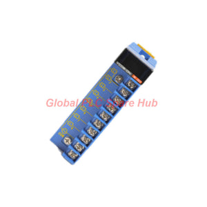
F3YC08-0N Yokogawa FA-M3 PLC Relay Module | 2A Switching Output
Manufacturer: Yokogawa
Product No.: F3YC08-0N
Condition: In stock
Product Type: Relay Module
Product Origin: SG
Payment: T/T, Western Union
Weight: 180g
Shipping port: Xiamen
Warranty: 12 months
Estimate delivery times: 12-26 days (International), 3-6 days (United States).
Return within 30 days of purchase. Duties & taxes are non-refundable.
Guaranteed Safe Checkout
F3YC08-0N | Yokogawa 8-Point Relay Output Module
The Yokogawa F3YC08-0N is an 8-point relay output module designed to switch compatible AC and DC loads in industrial automation systems. Its mechanical relay contacts provide electrical switching between the control system and external loads, with a rated load voltage of 5–24 V DC or 100–240 V AC.
Each output supports a maximum load current of 2 A, while the common circuit supports a maximum of 8 A. The module uses mechanical isolation, provides a maximum 10 ms response time for both switching transitions, and connects through a 10-point M3.5 screw terminal block. Relay selection requires attention to load current, inrush current, switching frequency, contact life, and the installation environment.
01 | Output Architecture and Electrical Limits
| Parameter | Specification |
|---|---|
| Manufacturer | Yokogawa |
| Model | F3YC08-0N |
| Product type | Relay contact output module |
| Output points | 8 |
| Points per common | 8 |
| Isolation method | Mechanical isolation |
| Rated load voltage | 5–24 V DC; 100–240 V AC |
| Maximum current per point | 2 A |
| Maximum current per common | 8 A |
| OFF-to-ON response time | 10 ms maximum |
| ON-to-OFF response time | 10 ms maximum |
| Mechanical life | 20 million operations or more |
| Electrical life | 100,000 operations or more |
| Surge protector | None |
| External power supply | Not required |
| CPU error output setting | HOLD/RESET not required, per supplied specification |
| Internal current consumption | 205 mA at 5 V DC |
| External connection | 10-point terminal block, M3.5 screw |
| Weight | Approximately 160 g |
02 | Relay Switching: What the Ratings Mean
| Design consideration | Engineering interpretation |
|---|---|
| 2 A per output | The load on an individual output must remain within the specified current limit and the applicable load conditions. |
| 8 A per common | The combined current of outputs sharing the common must not exceed the specified common limit. |
| AC and DC load ratings | Confirm that the actual load voltage and load type are within the module's specified rating. AC and DC switching behavior is not interchangeable. |
| 10 ms maximum response | Allow for relay switching time when designing control sequences. This is not the total PLC-to-load response time. |
| No built-in surge protector | Assess whether external suppression is required for inductive loads, following the load and equipment manufacturer's guidance. |
Important: The 2 A point rating and 8 A common rating are separate limits. Both must be observed. Motor loads, solenoid valves, contactor coils, lamps, and capacitive loads may have inrush or switching characteristics that require additional derating or an interposing relay. Do not size a circuit based on steady-state current alone.
03 | Contact Life and Environmental Constraints
The specified mechanical life is at least 20 million operations, while the specified electrical life is at least 100,000 operations. These figures describe different conditions: mechanical endurance does not guarantee the same number of operations while switching an electrical load. Actual electrical life depends on the load, switching frequency, voltage, current, and contact conditions.
- Dust and corrosive gases: The relays are not hermetically sealed. Contaminants can reduce contact reliability and service life.
- Silicone-containing atmospheres: Silicone gases may contribute to silicon dioxide deposits on relay contacts, potentially causing poor electrical contact.
- Low-current DC loads: The supplied documentation highlights particular contact reliability concerns in silicone-contaminated environments for loads below 24 V DC and 500 mA.
- High switching frequency: Frequent electrical switching can shorten contact life. Estimate expected operations over the maintenance interval before selecting relay outputs.
- Inductive loads: Evaluate the need for external suppression and verify the load manufacturer's requirements before wiring.
For environments containing silicone gases, heavy dust, or corrosive gases, the supplied manufacturer note recommends considering transistor output modules or other semiconductor-based alternatives. Verify that the alternative supports the required load voltage, current, and switching behavior.
04 | Model Code and Replacement Identification
- F3YC08 — Model designation for the 8-point relay output module.
- -0N — Suffix associated with the specified relay output configuration.
Before ordering a replacement, match the complete model code and confirm the controller/I/O platform, terminal arrangement, load type, and wiring scheme. A relay output module should not be substituted solely because another unit has eight channels or a similar terminal block.
05 | Compatible Load Types and Industrial Applications
- Control panels: Switching compatible AC or DC control circuits and auxiliary equipment.
- Solenoid valves: Operating suitable valve coils after checking coil current, inrush characteristics, and suppression requirements.
- Contactor coils: Providing control signals to appropriately rated contactors when the coil load is within the module's limits.
- Machine automation: Switching discrete loads used in machine sequencing and equipment-state control.
- Process equipment: Controlling compatible auxiliary devices in PLC-based process panels.
- Alarm and indication circuits: Switching suitable annunciators, indicators, and other discrete loads within the electrical ratings.
- Legacy system maintenance: Replacing a matching relay output module in an existing supported Yokogawa I/O configuration.
These are application examples, not a guarantee of direct compatibility with every device. Check the actual load current, voltage, inrush current, switching frequency, common grouping, and system documentation before connection.
06 | Commissioning Checklist for Controls Engineers
- Verify the hardware: Confirm that the installed Yokogawa system supports the F3YC08-0N and that the complete part number matches the replacement requirement.
- Isolate all circuits: Follow site lockout/tagout and electrical safety procedures before wiring or servicing the module.
- Check load ratings: Verify each load's operating voltage and steady-state and inrush currents. Ensure that no point exceeds 2 A and the shared common remains within 8 A.
- Inspect terminal wiring: Use the correct wiring diagram for the 10-point M3.5 terminal block. Confirm conductor sizing, polarity for DC circuits, and secure connections.
- Assess inductive loads: Determine whether external suppression is needed because the module has no specified built-in surge protector.
- Test each output: Command each channel individually and verify that the field load switches correctly.
- Validate the sequence: Confirm PLC logic, interlocks, and actual load response before returning the equipment to automatic operation.
07 | Troubleshooting Matrix
| Observed issue | Likely checks |
|---|---|
| Load does not energize | Verify the load supply, fuse or protective device, terminal wiring, PLC command, and load continuity. |
| Load remains energized after the OFF command | Check the control logic, external wiring, and whether the load is being supplied through another circuit. Isolate power before checking for welded relay contacts. |
| Intermittent switching | Inspect loose terminals, contact wear, contamination, coil inrush, and possible electrical interference. |
| Several outputs fail together | Check the shared common circuit, load supply, protective devices, connector/terminal integrity, and common-current loading. |
| Relay contacts have a shortened service life | Review load type, switching frequency, inrush current, suppression, and the presence of dust, corrosive gases, or silicone-containing vapors. |
| PLC output status changes but the load does not respond | Separate the logic command from the electrical output path. Measure the load supply and inspect the relay contact circuit using approved safe test procedures. |
Diagnostic limitation: The supplied specifications do not confirm dedicated per-channel diagnostic indicators or electronic contact-life monitoring. Use PLC status monitoring, electrical measurements, load checks, and physical inspection to locate faults. Relay contacts may require de-energized testing and safe isolation before continuity checks.
08 | Global PLC Spare HUB Review
The F3YC08-0N is a relay-based solution for applications that require discrete switching of compatible AC or DC loads. Its main selection advantage is the ability to switch a range of rated load voltages through mechanical contacts. However, the current limits, shared common, and relay contact life must be considered together when planning a replacement or new control panel.
In practical maintenance work, a failed load does not always indicate a failed output module. Check the external supply, fuse, wiring, load coil, and common circuit before replacing the relay module. If a relay output is used for frequent switching or low-current DC loads in a contaminated environment, evaluate whether a semiconductor output or an interposing relay is a better long-term choice.
09 | Procurement Checklist
- Confirm the full part number: F3YC08-0N.
- Verify the requirement for eight relay contact outputs.
- Check the intended AC/DC load voltage and current, including inrush.
- Confirm the 2 A per-point and 8 A per-common limits.
- Verify the terminal block, wiring diagram, and supported Yokogawa platform.
- Review environmental conditions and the expected switching frequency.
- Confirm whether external suppression or an alternative output technology is needed.
10 | Warranty and Shipping
- Warranty: 12 months, subject to the seller's warranty terms and conditions.
- Product condition and packing: New and original factory packing, subject to stock confirmation.
- Shipping methods: FedEx, UPS, and DHL.
- Dispatch: 24–48-hour dispatch may be available after order and stock confirmation.
- Order support: Provide the full model code and load/application details to help verify the replacement configuration.
11 | Frequently Asked Questions
Q1. Can all eight outputs carry 2 A at the same time?
Answer: Not at 2 A each. Although the maximum rating is 2 A per point, the shared common is limited to 8 A. The combined current of outputs on that common must remain within 8 A, so all eight channels cannot each carry 2 A simultaneously without exceeding the common limit.
Q2. Is this module suitable for directly switching a motor?
Answer: Do not assume direct motor switching is suitable from the stated current rating alone. Motor starting current and inductive switching stress can exceed the conditions implied by a simple resistive-load rating. Check the manufacturer's detailed load specifications and use a properly rated contactor or interposing device where required.
Q3. Why can a relay module fail even when the measured load current is below 2 A?
Answer: Load current is only one factor. Inrush current, inductive energy, switching frequency, contact contamination, and the shared common limit can also affect reliability. Review the load characteristics and installation environment, not just the steady-state current measurement.
Q4. What should be considered when replacing this module in a dusty or silicone-contaminated cabinet?
Answer: First assess whether the enclosure environment meets the module's requirements. The relays are not hermetically sealed, and silicone gases can lead to deposits on contact surfaces. Where contamination cannot be controlled, consider a compatible semiconductor output module or another suitable interface after verifying the electrical requirements.
Q5. How do I decide between a relay output and a transistor output for a replacement?
Answer: Compare the load voltage and current, AC/DC requirement, switching frequency, expected service life, environmental conditions, and response requirements. Relay outputs can support the specified AC and DC load ranges but have mechanical contacts and finite electrical life. Transistor outputs are generally better suited to frequent switching of compatible DC loads, but they do not automatically replace an AC-capable relay output. Confirm platform compatibility and load ratings before changing output technology.
Request a Quote for Yokogawa F3YC08-0N
Contact Global PLC Spare HUB for pricing, availability, and replacement verification for the Yokogawa F3YC08-0N relay output module. Include the complete model number and load details to support the selection process. FedEx, UPS, and DHL shipping options are available subject to order arrangements.
Tags
Q: Are these parts 100% original and new?
A: Yes. Every component is guaranteed to be 100% original, brand-new, and factory-sealed. We also provide a 12-month comprehensive warranty for your peace of mind.
Q: How fast is the shipping to my country?
A: For in-stock items, we offer same-day dispatch. International express shipping (DHL/FedEx/UPS) typically delivers within 3–5 business days worldwide.
Q: Can I get a formal quotation with shipping costs?
A: Absolutely. Our sales team is ready to provide a detailed Proforma Invoice (PI) including the most competitive shipping rates for your location.
Q: Do you offer discounts for bulk orders?
A: We provide volume-based pricing for large projects or multiple-item orders. Please contact us to get our Best Price Guarantee.
12-Month Comprehensive Warranty
Every part supplied by Global PLC Spare Hub is covered by a 12-month warranty from the date of invoice.
- Coverage: Functional defects and hardware failures under normal operating conditions.
- Commitment: We provide immediate repair, replacement, or a full refund for any verified defective components to minimize your operational downtime.
Returns & Exchange Policy
We offer a 30-day return policy to ensure you receive the exact part your system requires.
- Eligibility: Returns are accepted for uninstalled items in their original, factory-sealed packaging.
- RMA Process: Please contact our support team to obtain a Return Merchandise Authorization (RMA) number before shipping.
- Fast Processing: Refunds or exchanges are processed within 3–5 business days after the returned item passes our technical inspection.
Need Technical Assistance?Not sure if this part is compatible with your system? [Consult our Engineers] before purchasing to ensure 100% compatibility.
People Also Bought


