


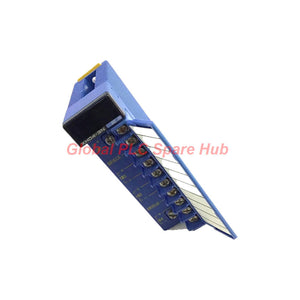
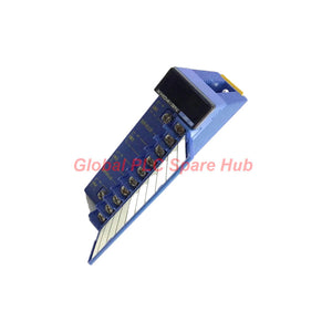
F3XH04-3N Yokogawa FA-M3 Pulse Input Module 24V DC 4-Channel
Manufacturer: Yokogawa
Product No.: F3XH04-3N
Condition: In stock
Product Type: Pulse Input Module
Product Origin: JP
Payment: T/T, Western Union
Weight: 130g
Shipping port: Xiamen
Warranty: 12 months
Estimate delivery times: 12-26 days (International), 3-6 days (United States).
Return within 30 days of purchase. Duties & taxes are non-refundable.
Guaranteed Safe Checkout
Yokogawa F3XH04-3N | High-Speed Pulse Input for FA-M3
The Yokogawa F3XH04-3N is a 4-channel high-speed digital input module for the FA-M3 programmable controller platform. It accepts 24 V DC signals and detects short-duration pulses that may be missed during a normal PLC scan.
With a minimum input pulse width of 50 μs, photocoupler isolation, and four independent input circuits, this module supports fast event detection in industrial automation systems. Its pulse-capture and interrupt functions help the controller respond to brief input transitions without relying solely on routine scan-based processing.
Engineering highlight: Pulse-capture and interrupt functions cannot operate simultaneously. Select the required operating mode according to the application, configure the module correctly, and verify the signal timing during commissioning.
01 | Signal Acquisition at a Glance
| Function | Engineering Value | Why It Matters |
|---|---|---|
| Input channels | 4 independent inputs | Allows signals from separate field devices to be connected to individual input points. |
| Rated input voltage | 24 V DC | Suitable for compatible 24 V DC industrial switching signals. |
| Minimum pulse width | 50 μs | Supports detection of short pulses that may occur between routine PLC scans. |
| Input response time | 50 μs maximum, OFF to ON and ON to OFF | Provides a reference for evaluating input timing requirements. |
| Input hold time | 512 μs after an OFF-to-ON transition | Holds the detected input signal for the specified period to support processing. |
| Isolation | Photocoupler isolation | Provides electrical isolation between the input circuitry and internal logic. |
| Operating mode selection | DIP switches | Used to select the supported pulse-capture or interrupt function. |
02 | Electrical Interface and Switching Thresholds
| Parameter | Specification |
|---|---|
| Input type | DC voltage |
| Rated input voltage | 24 V DC |
| Operating voltage range | 20.4–26.4 V DC |
| Rated input current | 11.2 mA per point at 24 V DC |
| Input impedance | 2.1 kΩ |
| ON-state threshold | 16.0 V DC minimum; 7.2 mA minimum |
| OFF-state threshold | 6.0 V DC maximum; 2.5 mA maximum |
| Current consumption | 30 mA at 5 V DC |
| External connection | 10-point terminal block with M3.5 screws |
| Weight | Approximately 130 g |
Signal-level check: The stated ON and OFF thresholds define the expected input states. When a field signal falls between the specified OFF and ON limits, do not assume a guaranteed logic state. Check the sensor output, voltage drop, common wiring, and signal waveform.
03 | Timing Logic: From Field Pulse to PLC Processing
The module is designed for applications where short input events require more attention than ordinary scan-based digital input processing can provide.
- Field event: A photoelectric sensor, proximity switch, or compatible pulse source generates a 24 V DC transition.
- Electrical detection: The input circuit evaluates the voltage and current against its specified switching thresholds.
- High-speed capture: The pulse-capture function detects a qualifying transition even when its ON duration is shorter than the normal PLC scan period.
- Processing support: The detected state is held for 512 μs after an OFF-to-ON transition, according to the module specification.
- Application response: The PLC program processes the captured input according to the configured system logic.
The F3XH04-3N also supports an interrupt function. This can be useful when the application requires event-driven processing. The pulse-capture and interrupt functions are mutually exclusive, so the required mode must be selected before commissioning.
Timing caution: The 50 μs minimum pulse width is an input detection specification, not a guarantee that the complete PLC application will respond within 50 μs. Program execution, interrupt handling, communication, and output-device response introduce additional timing considerations.
04 | Configuration and Wiring Requirements
| Configuration Item | Requirement |
|---|---|
| Module model | F3XH04-3N |
| Module family | Yokogawa FA-M3 |
| Pulse-capture selection | Selected by DIP switches |
| Interrupt selection | Selected by DIP switches; set for each point through the FA-M3 programming tool WideField3, according to the supplied configuration information |
| Field terminal type | 10-point terminal block, M3.5 screw connection |
| Applicable conductor size | 0.33–0.82 mm² |
| Wiring method | Solderless terminal connection |
| Recommended crimping torque | 0.8 N·m (8 kgf·cm, 6.9 lbf·in) |
| Listed solderless terminals | V1.25-M3 (Japan Solderless Terminal Mfg. Co., Ltd.) or RAV1.25-3.5 (Nippon Tanshi Co., Ltd.) |
The terminal block includes terminals intended for shielded cable connections. Follow the equipment wiring diagrams for shield termination, signal routing, and grounding. Keep high-speed signal wiring away from strong electrical noise sources where practical.
Before energizing: Confirm terminal assignments, field polarity, input voltage, DIP switch positions, and program configuration against the applicable Yokogawa documentation. Do not infer terminal functions from terminal count alone.
05 | FA-M3 Integration and Application Fit
The manufacturer specifies no restriction on the type of CPU module that can be used with the F3XH04-3N. The complete installation must still comply with the selected FA-M3 configuration, system documentation, and application requirements.
- Photoelectric sensing: Captures short pulses from photo-micro switches and compatible photoelectric sensors.
- Proximity detection: Detects brief switching events from compatible 24 V DC proximity sensors.
- Part counting: Supports fast event acquisition on production lines where short sensor pulses may be missed by routine scan-based inputs.
- Position and sequence detection: Monitors short-duration switching events used in indexing, sorting, and machine sequencing.
- Event-driven control: Supports interrupt-based processing where the application benefits from a configured response to an input event.
- Industrial inspection equipment: Acquires rapid sensor transitions for synchronized handling or inspection sequences.
Selection boundary: This is a discrete DC input module, not a general-purpose analog input module or a dedicated high-speed counter specification. If the application requires frequency measurement, pulse accumulation, quadrature decoding, or a defined maximum count rate, verify those capabilities separately before selection.
06 | Operating Environment
| Environmental Parameter | Specification |
|---|---|
| Operating ambient temperature | 0 to 55°C |
| Storage temperature | -20 to 75°C |
| Operating relative humidity | 10–90% RH, non-condensing |
| Storage relative humidity | 10–90% RH, non-condensing |
| Atmosphere | Must be free of corrosive gases, flammable gases, and heavy dust |
Install the module in an environment that meets the specified temperature, humidity, and atmospheric conditions. Assess enclosure ventilation, cabinet contamination, and electrical noise where high-speed signals are involved.
07 | Diagnostic Matrix for Commissioning and Maintenance
| Symptom | Possible Cause | Recommended Diagnostic Action |
|---|---|---|
| A short pulse is not detected | Pulse width below the supported minimum, incorrect mode selection, or unsuitable signal level | Measure the pulse waveform and verify the 50 μs minimum pulse width, input thresholds, and DIP switch configuration. |
| Input state appears inconsistent | Field voltage near the switching threshold, noise, poor terminal contact, or unstable sensor output | Measure voltage at the module terminals during switching. Inspect the wiring, terminal tightness, and sensor supply. |
| Interrupt routine does not execute as expected | Incorrect interrupt configuration, program setup, or selected operating mode | Verify the point configuration in WideField3, DIP switch settings, and the application’s interrupt handling logic. |
| Pulse-capture behavior is unavailable | Interrupt mode selected instead of pulse-capture mode, or incorrect setup | Confirm the required function and recheck the mutually exclusive mode selection. |
| Input remains OFF despite a sensor event | Incorrect polarity, insufficient ON-state voltage/current, broken wiring, or an incompatible output type | Check the sensor output specification and measure the voltage and current delivered to the input. |
| Intermittent false transitions occur | Electrical interference, poor shielding, loose wiring, or unstable field signals | Inspect cable routing, shielding, terminal connections, and the sensor waveform under operating conditions. |
Diagnostic method: Start at the field sensor and verify its waveform. Next, confirm voltage and current at the module terminals. Then check the operating mode, PLC configuration, and program behavior. This sequence helps separate field wiring faults from configuration or application-logic problems.
The module’s high-speed input function does not by itself identify the root cause of a machine fault. System diagnostics depend on the PLC program, available status information, the connected sensor, and the overall control architecture.
08 | Global PLC Spare HUB's Insight
When selecting a high-speed input module, engineers should compare the shortest valid field pulse with the input module’s detection requirements and the PLC application's response time. A short input response specification is only one part of the timing chain.
- For high-speed photoelectric sensing: Confirm that the sensor produces a pulse of sufficient width and meets the module’s voltage and current thresholds.
- For production-line counting: Evaluate the minimum interval between events as well as pulse width. Confirm that the program can process events at the required rate.
- For interrupt-driven applications: Review the interrupt configuration, program execution, and potential event frequency before enabling the function.
- For replacement projects: Match the exact model code, terminal arrangement, input voltage, and required operating mode. Check the existing program before replacing a module with a different input type.
- For fault investigation: Use an oscilloscope or suitable measurement instrument to confirm the actual pulse waveform when intermittent events are difficult to reproduce.
The Yokogawa F3XH04-3N is most appropriate when the control system needs reliable detection of short 24 V DC input pulses. Applications that require pulse accumulation or precise frequency measurement should be checked against the specifications of the complete FA-M3 system.
09 | Five Professional FAQs
Q1. How can I determine whether the F3XH04-3N is suitable for my sensor?
Check the sensor’s output type, supply voltage, ON-state voltage and current, OFF-state leakage, and minimum pulse width. The module is designed for 24 V DC inputs, with an operating voltage range of 20.4–26.4 V DC. Confirm that the sensor output meets the module’s switching thresholds under actual load conditions.
Q2. Will the module reliably capture pulses generated at a very high repetition rate?
The 50 μs minimum pulse width describes the specified pulse detection capability, but it does not establish a maximum event frequency for every application. Check the pulse period, OFF time, event spacing, PLC processing load, and required counting behavior. Obtain the applicable manufacturer specifications if the application depends on a guaranteed maximum event rate.
Q3. What should I check before changing from pulse-capture mode to interrupt mode?
Confirm which function the control program requires and review the existing DIP switch settings. The two functions cannot be used simultaneously. Check the per-point interrupt setup in WideField3 and validate the program response after making any configuration changes.
Q4. Is this module a direct replacement for a standard 24 V DC digital input module?
Not necessarily. Although it accepts 24 V DC signals, it includes high-speed pulse-capture and interrupt features that may require specific configuration and program logic. Before replacement, verify the FA-M3 system configuration, terminal wiring, input behavior, and application requirements.
Q5. What details should I provide when requesting a quotation for this module?
Provide the full model number F3XH04-3N, required quantity, destination country, and any timing or application requirements. If replacing an installed unit, include the controller model, existing module model, and a clear nameplate photo where available. These details help verify the requested configuration and reduce selection errors.
10 | Ordering, Warranty and Shipping
- Manufacturer: Yokogawa
- Model: F3XH04-3N
- Series: FA-M3
- Product type: High-Speed Pulse Input Module
- Configuration: 24 V DC, 4 independent input channels
- Warranty: 12 months, subject to the seller’s written warranty terms.
- Shipping options: FedEx, UPS, and DHL, subject to destination and service availability.
- Dispatch target: 24–48 hours after order confirmation, subject to stock availability and payment clearance.
Request a quote for Yokogawa F3XH04-3N. Include your required quantity, destination, and application details. For replacement orders, provide the existing module model and relevant FA-M3 system information to help confirm compatibility before shipment.

Tags
Q: Are these parts 100% original and new?
A: Yes. Every component is guaranteed to be 100% original, brand-new, and factory-sealed. We also provide a 12-month comprehensive warranty for your peace of mind.
Q: How fast is the shipping to my country?
A: For in-stock items, we offer same-day dispatch. International express shipping (DHL/FedEx/UPS) typically delivers within 3–5 business days worldwide.
Q: Can I get a formal quotation with shipping costs?
A: Absolutely. Our sales team is ready to provide a detailed Proforma Invoice (PI) including the most competitive shipping rates for your location.
Q: Do you offer discounts for bulk orders?
A: We provide volume-based pricing for large projects or multiple-item orders. Please contact us to get our Best Price Guarantee.
12-Month Comprehensive Warranty
Every part supplied by Global PLC Spare Hub is covered by a 12-month warranty from the date of invoice.
- Coverage: Functional defects and hardware failures under normal operating conditions.
- Commitment: We provide immediate repair, replacement, or a full refund for any verified defective components to minimize your operational downtime.
Returns & Exchange Policy
We offer a 30-day return policy to ensure you receive the exact part your system requires.
- Eligibility: Returns are accepted for uninstalled items in their original, factory-sealed packaging.
- RMA Process: Please contact our support team to obtain a Return Merchandise Authorization (RMA) number before shipping.
- Fast Processing: Refunds or exchanges are processed within 3–5 business days after the returned item passes our technical inspection.
Need Technical Assistance?Not sure if this part is compatible with your system? [Consult our Engineers] before purchasing to ensure 100% compatibility.
People Also Bought


