


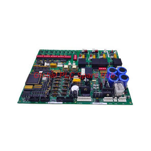
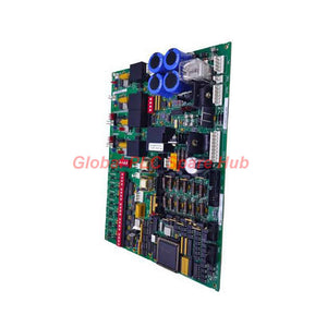
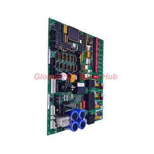
DS200DCFBG1BKC GE Mark V DC Feedback Power Supply Board
Manufacturer: GE
Product No.: DS200DCFBG1BKC
Condition: In stock
Product Type: Power Supply Board
Product Origin: USA
Payment: T/T, Western Union
Weight: 500g
Shipping port: Xiamen
Warranty: 12 months
Estimate delivery times: 12-26 days (International), 3-6 days (United States).
Return within 30 days of purchase. Duties & taxes are non-refundable.
Guaranteed Safe Checkout
Product Overview
- The DS200DCFBG1BKC functions as a highly integrated DC Feedback Power Supply Board developed by General Electric.
- This critical DCFB module serves dual roles by generating localized control-level voltages and processing core analog telemetry feedback.
- It provides critical power distribution to drive system elements while regulating real-time armature and motor field signal transitions.
Engineering Technical Specifications
- Manufacturer: General Electric (GE)
- Model Identification: DS200DCFBG1BKC
- System Compatibility Matrix: Mark V Speedtronic, AC2000, CB2000, DC2000, FC2000, ME2000, EX2000, and IGBT drives
- Functional Class: DC Feedback Power Supply Board (DCFB)
- Primary Input Voltage: 38 VAC and 115 VAC (or 24 VDC nominal) sourced from the Control Power Transformer (CPT)
- Regulated Control Outputs: +5 VDC (4 A capacity), +/-15 VDC, and +/-24 VDC rails
- Enclosure Fan Power Rails: Dedicated 115 VAC distribution line
- Hardware Revision Level: Revision B, featuring specific BKC sub-artwork modifications
- Configurable Jumper Matrix: 13 onboard manual hardware jumpers (specific to revision BKC and later)
- Attenuation DIP Switches: 7 multi-position DIP switch blocks for field scaling adjustments
- Interface Interconnects: 18 plug-style connector blocks alongside 9 rigid male stab terminals
- Physical Shipping Configuration: Weight: 1.3 lbs | Dimensions: 20 inches x 16 inches x 16 inches
Circuit Topology & Signal Telemetry
- The DS200DCFBG1BKC architecture houses advanced Voltage-Controlled Oscillator (VCO) circuits that convert analog motor feedback into precise frequency signals.
- Operating at a nominal baseline frequency of 250 kHz, these VCOs modulate an active output range spanning 0 to 500 kHz.
- Telemetry strings are fed directly into the primary SDCC or LDCC Drive Control Cards via the 1PL ribbon connector.
- Onboard scaling attenuation for the output bridge and motor voltage loops is governed directly by manual DIP switches SW4 and SW5.
Target Equipment & Application Scenarios
- Mark V Speedtronic gas or steam turbine control panel integration
- Voltage feedback scaling inside GE DC2000 and AC2000 high-power drive cabinets
- Motor field excitation management within EX2000 control loops
- Enclosure cooling fan distribution grids demanding local inline fuse isolation
Diagnostic Capabilities & System Protection
- Fault Isolation Architecture: Uses three dedicated sub-fuses (FU1, FU2, FU3) to isolate independent board voltage distribution lines.
- FU1 Protection: A 1/2 A, 2AG fuse safeguarding the 115 VAC enclosure fan output line.
- FU2 & FU3 Protection: Dual 7 A, 2AG fuses safeguarding the internal DC regulator sub-circuit tracks.
- Optical Telemetry: Red LED indicators CR51 and CR55 indicate blown states for FU2/FU3; neon lamp LT1 tracks active FU1 line faults.
- Microprocessor Watchdog: The board toggles the /PSEN signal line to a TTL high state if the +5 VDC rail drops regulation, automatically resetting the host SDCC/LDCC processor.
- Analog Testpoints: 5 hardware testpoints facilitate bare-board volt testing, board common tracking, and ACCT status verification.
Installation & System Commissioning Parameters
- Isolate all raw power lines upstream before positioning the DS200DCFBG1BKC module inside the cabinet framework.
- Consult GEI-100028 instruction parameters to ensure exact pairing with matching SDCC firmware versions.
- Set all 13 Berg-type jumpers to match the original plant schematic layout before introducing line voltage.
- Ensure the 1PL connector ribbon is locked down tightly to prevent VCO frequency signal degradation.
Global PLC Spare HUB's Insight
- The GE DS200DCFBG1BKC feedback assembly is a masterclass in deterministic hardware fail-safe engineering.
- By utilizing analog VCO frequency conversion rather than standard multi-bit digital buses, GE avoids high-frequency electromagnetic noise interference common in large SCR and IGBT drive environments.
- The inclusion of the 13th jumper on the BKC revision gives technicians better control over specialized field-shunt voltage matching, enhancing operational stability under high thermal fluctuations.
Procurement & Express Logistics Terms
- Packaging Standards: One factory-tested DS200DCFBG1BKC power supply board wrapped in a certified anti-static barrier.
- Warranty Policy: 12-month comprehensive warranty coverage addressing operational or technical defects.
- Global Shipping Networks: Express shipping available through FedEx, UPS, and DHL air freight operations.
- Warehouse Dispatch: Complete validation and shipment execution completed within 24 to 48 hours of order verification.
Technical Buying Guide
- Confirm your exact legacy suffix; older boards lacking the BKC artwork designation feature only 12 configuration jumpers instead of 13.
- Examine the current state of your drive control card's /PSEN reset loop to see if power supply degradation is causing intermittent processor drops.
- Verify whether your system is an EX2000 application, as this framework utilizes the DCFB module configuration for separate structural parameters compared to standard AC/DC drives.
FAQ
Why does the BKC revision of this board feature 13 jumpers instead of the standard 12?
The 13th jumper block on the BKC revision provides additional hardware-level scaling flexibility for specialized voltage and current feedback circuits used in later drive control revisions.
What happens to the host turbine system if the onboard +5 VDC supply drops out of regulation?
The board changes the /PSEN signal on connector 2PL to a TTL high state, forcing an immediate safety reset of the main SDCC or LDCC microprocessor to prevent uncontrolled operations.
How can an instrument engineer verify the integrity of the bridge voltage feedback loop locally?
You can connect an ac-coupled oscilloscope to testpoint TP37 on the parent SDCC/LDCC board to view the reconstructed diagnostic frequency signal coming from the board's VCO.
What specific functions do the onboard DIP switches SW6 and SW4 manage?
SW4 controls the input voltage scaling factor for the output bridge VCO loop, while SW6 actively modifies and scales the motor voltage feedback loop signals before frequency conversion.
Can this board be used to supply field power directly to larger SCR motor modules?
No, the board drives the control-level motor field circuits and SCR gate pulse generator driver circuits, but it does not supply the primary heavy excitation current directly to the main SCR module.
Tags
Q: Are these parts 100% original and new?
A: Yes. Every component is guaranteed to be 100% original, brand-new, and factory-sealed. We also provide a 12-month comprehensive warranty for your peace of mind.
Q: How fast is the shipping to my country?
A: For in-stock items, we offer same-day dispatch. International express shipping (DHL/FedEx/UPS) typically delivers within 3–5 business days worldwide.
Q: Can I get a formal quotation with shipping costs?
A: Absolutely. Our sales team is ready to provide a detailed Proforma Invoice (PI) including the most competitive shipping rates for your location.
Q: Do you offer discounts for bulk orders?
A: We provide volume-based pricing for large projects or multiple-item orders. Please contact us to get our Best Price Guarantee.
12-Month Comprehensive Warranty
Every part supplied by Global PLC Spare Hub is covered by a 12-month warranty from the date of invoice.
- Coverage: Functional defects and hardware failures under normal operating conditions.
- Commitment: We provide immediate repair, replacement, or a full refund for any verified defective components to minimize your operational downtime.
Returns & Exchange Policy
We offer a 30-day return policy to ensure you receive the exact part your system requires.
- Eligibility: Returns are accepted for uninstalled items in their original, factory-sealed packaging.
- RMA Process: Please contact our support team to obtain a Return Merchandise Authorization (RMA) number before shipping.
- Fast Processing: Refunds or exchanges are processed within 3–5 business days after the returned item passes our technical inspection.
Need Technical Assistance?Not sure if this part is compatible with your system? [Consult our Engineers] before purchasing to ensure 100% compatibility.
People Also Bought


