


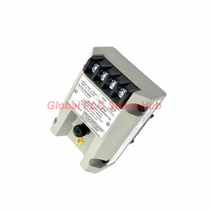
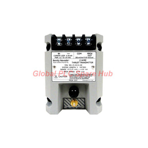
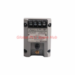
991-25-50-01-05 Bently Nevada 991 Thrust Transmitter
Manufacturer: Bently Nevada
Product No.: 991-25-50-01-05
Condition: In stock
Product Type: Thrust Transmitter
Product Origin: USA
Payment: T/T, Western Union
Weight: 430g
Shipping port: Xiamen
Warranty: 12 months
Estimate delivery times: 12-26 days (International), 3-6 days (United States).
Return within 30 days of purchase. Duties & taxes are non-refundable.
Guaranteed Safe Checkout
Bently Nevada 991-25-50-01-05 | Axial Thrust Transmitter
The Bently Nevada 991-25-50-01-05 is a DIN-rail-mounted transmitter designed for axial position and thrust-related displacement monitoring. It accepts one compatible 3300 NSv proximity probe and extension cable, then converts the measured displacement into a two-wire 4–20 mA DC signal.
This configuration uses a symmetrical 25-0-25 mil full-scale option and a 5.0 m system-length option. It supports integration with compatible PLC, DCS, and machinery monitoring inputs. Its NOT OK function drives the current output below 3.6 mA when a qualifying measurement-system fault occurs.
Configuration Map | Decode the Ordering Number
| Code | Option | Configuration Meaning |
|---|---|---|
| 991 | Model | Thrust transmitter |
| 25 | Full-scale option | 25-0-25 mils |
| 50 | System-length option | 5.0 m (16.4 ft) |
| 01 | Mounting option | 35 mm DIN-rail clips |
| 05 | Agency approval option | CSA Division 2, ATEX Zone 0, ATEX Zone 2, and ABS maritime approval, as specified for this option |
Ordering-code structure:
- 991 — transmitter model
- -25 — 25-0-25 mil full-scale option
- -50 — 5.0 m system-length option
- -01 — 35 mm DIN-rail mounting option
- -05 — specified agency approval package
Always verify the complete ordering code and the applicable approval documents before replacing a transmitter. Hazardous-area and maritime approvals apply only under their stated conditions and installation requirements.
Technical Specification Register
| Parameter | Specification |
|---|---|
| Manufacturer | Bently Nevada |
| Model | 991-25-50-01-05 |
| Product Type | Thrust transmitter |
| Measurement Purpose | Axial position / thrust-related displacement |
| Compatible Input | One non-contacting 3300 NSv proximity probe and extension cable |
| Full-Scale Option | 25-0-25 mils |
| Linear Range | 0.25–1.65 mm for Prox Out; suitable for 0.6-0-0.6 mm or 25-0-25 mil current-loop linear ranges |
| Output | 4–20 mA DC, two-wire configuration |
| Supply Voltage | +12 to +35 V DC at transmitter terminals |
| Typical Loop Accuracy | Within ±1.5% of specified full-scale range |
| Accuracy Test Conditions | Rated from TEST signal input to voltage measured across a 250 Ω loop resistance |
| Maximum Loop Resistance | 1,000 Ω including cable at 35 V DC |
| Typical Current Limiting | 23 mA |
| Zero and Span | Non-interacting external adjustments |
| NOT OK Output Response | Output falls below 3.6 mA within 100 μs after a NOT OK condition occurs |
| Signal Recovery | Output restored within 0.1 seconds after the NOT OK condition is removed |
| Mounting | 35 mm DIN rail |
| Transmitter Operating Temperature | −35°C to +85°C (−31°F to +185°F) |
| Transmitter Storage Temperature | −51°C to +100°C (−60°F to +212°F) |
| Weight | 0.43 kg (0.9 lbm) |
| Approval Option | CSA Division 2, ATEX Zone 0, ATEX Zone 2, and ABS maritime approval, subject to official documentation |
Range clarification: The 25-0-25 mil option describes a bidirectional measurement range around a central reference. Confirm the configured engineering range and scaling in the receiving system. Do not assume that every 4–20 mA channel automatically interprets the signal as a centered axial range.
How It Fits into an Axial Position Monitoring Loop
The transmitter converts a proximity probe measurement into a current signal that a compatible control or monitoring system can read. Accurate results depend on the probe assembly, mechanical target, supply voltage, loop resistance, and channel scaling.
- Probe measurement: The compatible 3300 NSv probe senses the position of a conductive target without contact.
- Signal conversion: The transmitter converts the probe signal into a 4–20 mA output across the configured measurement range.
- System interface: A PLC, DCS, or monitoring input receives the current signal for display, trending, and alarm logic.
- Fault signaling: A qualifying NOT OK condition drives the output below 3.6 mA, allowing compatible receiving equipment to identify an abnormal measurement state.
- Field adjustment: External zero and span adjustments support calibration of the measurement output within the manufacturer's procedure.
The transmitter supplies an axial displacement-related signal. It does not independently determine thrust force. Mechanical thrust interpretation depends on the machine design, probe location, target geometry, and configured alarm limits.
Where Engineers Commonly Apply This Transmitter
- Steam and gas turbines: Monitor axial shaft position as part of a broader machinery condition monitoring arrangement.
- Industrial compressors: Provide axial displacement data to compatible control and monitoring systems.
- Large pumps and rotating machinery: Track changes in shaft position where the equipment design supports proximity-probe measurement.
- Power generation equipment: Integrate axial position measurements into operator displays, trend histories, and engineered alarm logic.
- Marine machinery applications: Consider use where the required ABS approval and installation conditions are verified for the specific installation.
- Plant retrofits: Replace a matching transmitter where the probe system, range, mounting, power supply, and approvals align with the existing design.
Installation and Commissioning: Practical Checks
- Confirm the measurement design. Verify the required axial measurement range, the probe's position relative to the target, and the machine manufacturer's measurement recommendations.
- Check the complete sensor assembly. Confirm the 3300 NSv probe and extension cable are compatible with the 5.0 m system-length configuration.
- Inspect DIN-rail mounting. Secure the transmitter using the specified 35 mm DIN-rail clips and maintain access for wiring and adjustment.
- Verify the DC supply. Measure the voltage at the transmitter terminals. Ensure it remains within +12 to +35 V DC under operating load.
- Calculate loop resistance. Include field wiring, receiving-input resistance, and other series devices. The maximum stated resistance is 1,000 Ω at 35 V DC.
- Configure the analog input. Set the receiving channel for 4–20 mA and enter the correct bidirectional range and engineering units.
- Check zero and span. Follow the manufacturer's calibration procedure. Avoid adjusting the transmitter to compensate for a mechanical alignment or probe-gap problem.
- Validate fault handling. Confirm that the receiving system interprets current below 3.6 mA as intended and that recovery behavior matches the configured logic.
For hazardous-area installations, confirm the certificate, equipment marking, wiring method, and installation conditions against the actual site classification. The presence of an approval option does not by itself establish suitability for every hazardous location.
Field Diagnostics | From Symptom to Verification
| Symptom | Potential Cause | Recommended Check |
|---|---|---|
| Current output below 3.6 mA | NOT OK condition, probe fault, cable fault, or measurement-chain problem | Verify supply voltage, probe and extension-cable connections, and the manufacturer's fault-check procedure. |
| Current reading is stuck at one value | Input signal issue, incorrect wiring, or a problem with the probe or target | Check the loop current, inspect connections, and compare the measurement with a verified mechanical reference where available. |
| Axial reading has a consistent offset | Incorrect zero setting, probe positioning, target reference, or channel scaling | Review the machine's reference position, probe installation, transmitter zero, and receiving-system range. |
| Reading changes after maintenance | Probe position changed, wiring disturbed, or configuration altered | Compare pre- and post-maintenance records, inspect mounting and cable routing, and verify zero and span. |
| Current signal is unstable | Loose connections, unstable supply, electrical interference, or mechanical movement | Measure supply voltage under load, inspect terminals and shielding practices, and compare local measurements with the trend. |
| PLC/DCS display disagrees with the measured loop current | Incorrect channel scaling, range direction, or engineering-unit conversion | Verify the 4–20 mA input configuration and confirm that the bidirectional 25-0-25 mil range is mapped correctly. |
Diagnostic caution: The NOT OK output helps identify a qualifying abnormal measurement condition, but it does not guarantee detection of every possible mechanical, wiring, or control-system fault. Diagnose the complete measurement loop rather than relying on current output alone.
Global PLC Spare HUB's Insight
For axial position monitoring, correct reference setup matters as much as the transmitter's electrical performance. A 25-0-25 mil range is centered around a reference point, so engineers must confirm the zero position and range direction before assigning alarm thresholds. A reversed or incorrectly scaled PLC/DCS channel can make normal shaft movement appear abnormal—or hide a meaningful change.
During a transmitter replacement, retain the original probe gap, cable identification, channel scaling, and calibration records where available. After installation, compare the displayed value against the transmitter loop current and the machine's documented reference position. If the reading changes after maintenance, investigate probe positioning and scaling before altering the span.
For turbine, compressor, and other critical rotating machinery, integrate the measurement into an engineered monitoring strategy. Confirm that alarm settings, trip logic, and any required independent protection functions follow the equipment manufacturer's and site's approved design.
Frequently Asked Questions
Q1: How can I tell whether a centered 25-0-25 mil range is configured correctly in my DCS?
Review the channel's lower and upper engineering limits, zero reference, and signal direction. Confirm the mapping against the transmitter configuration and a known reference condition. Do not assume a standard 4–20 mA input automatically supports a centered range.
Q2: What should I compare when the new transmitter does not match the old unit's reading?
Compare the full ordering code, probe and extension-cable combination, probe position, zero and span settings, and receiving-channel scaling. Record loop current and displayed engineering units at the same operating condition to isolate the source of the discrepancy.
Q3: Does the 5.0 m system-length option mean I can use any 5 m cable?
No. System length refers to the compatible probe and extension-cable arrangement specified by the manufacturer. Confirm cable type, probe model, and the approved combined system configuration instead of selecting a cable based only on physical length.
Q4: How should I assess whether this model suits a marine or hazardous-area installation?
Match the equipment marking and approval documents to the installation's actual classification and applicable requirements. Confirm the full model suffix, environmental conditions, mounting, wiring method, and any vessel or site-specific approval requirements before purchase.
Q5: What information helps prevent ordering the wrong replacement transmitter?
Provide the complete model number, required axial range, installed probe and extension-cable details, mounting arrangement, supply voltage, analog input configuration, and required approvals. If possible, include the existing transmitter's nameplate information and the receiving channel's configured range.
Warranty, Shipping, and Package Details
- Product: Bently Nevada 991-25-50-01-05 thrust transmitter
- Warranty: 12-month warranty, subject to the seller's applicable terms and conditions.
- Shipping options: FedEx, UPS, and DHL, subject to destination and shipment arrangements.
- Package contents: One transmitter. Probe, extension cable, and other accessories are included only when explicitly listed in the quotation.
- Order verification: Provide the complete model and application details to help confirm configuration compatibility and availability.
Request a quotation from Global PLC Spare HUB for the 991-25-50-01-05. Share your probe-system details and required approval conditions so the configuration can be checked before ordering.

Tags
Q: Are these parts 100% original and new?
A: Yes. Every component is guaranteed to be 100% original, brand-new, and factory-sealed. We also provide a 12-month comprehensive warranty for your peace of mind.
Q: How fast is the shipping to my country?
A: For in-stock items, we offer same-day dispatch. International express shipping (DHL/FedEx/UPS) typically delivers within 3–5 business days worldwide.
Q: Can I get a formal quotation with shipping costs?
A: Absolutely. Our sales team is ready to provide a detailed Proforma Invoice (PI) including the most competitive shipping rates for your location.
Q: Do you offer discounts for bulk orders?
A: We provide volume-based pricing for large projects or multiple-item orders. Please contact us to get our Best Price Guarantee.
12-Month Comprehensive Warranty
Every part supplied by Global PLC Spare Hub is covered by a 12-month warranty from the date of invoice.
- Coverage: Functional defects and hardware failures under normal operating conditions.
- Commitment: We provide immediate repair, replacement, or a full refund for any verified defective components to minimize your operational downtime.
Returns & Exchange Policy
We offer a 30-day return policy to ensure you receive the exact part your system requires.
- Eligibility: Returns are accepted for uninstalled items in their original, factory-sealed packaging.
- RMA Process: Please contact our support team to obtain a Return Merchandise Authorization (RMA) number before shipping.
- Fast Processing: Refunds or exchanges are processed within 3–5 business days after the returned item passes our technical inspection.
Need Technical Assistance?Not sure if this part is compatible with your system? [Consult our Engineers] before purchasing to ensure 100% compatibility.
People Also Bought


