


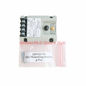
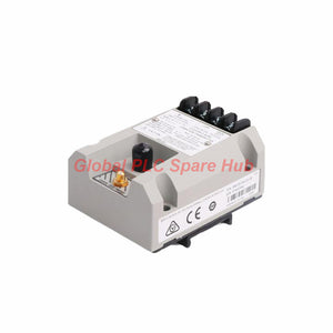
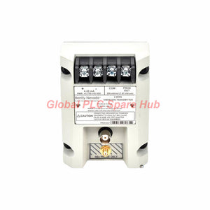
990-10-50-03-01 Bently Nevada 990 Vibration Transmitter
Manufacturer: Bently Nevada
Product No.: 990-10-50-03-01
Condition: In stock
Product Type: Vibration Transmitter
Product Origin: USA
Payment: T/T, Western Union
Weight: 430g
Shipping port: Xiamen
Warranty: 12 months
Estimate delivery times: 12-26 days (International), 3-6 days (United States).
Return within 30 days of purchase. Duties & taxes are non-refundable.
Guaranteed Safe Checkout
Bently Nevada 990-10-50-03-01 | 990 Vibration Transmitter
The Bently Nevada 990-10-50-03-01 is a two-wire vibration transmitter designed to interface with one compatible 3300 NSv proximity probe and its extension cable. It converts the probe measurement into a 4–20 mA DC signal for PLC, DCS, and machinery monitoring systems.
This configuration provides a full-scale range of 0–10 mils peak-to-peak (0–250 μm peak-to-peak), a 5.0 m system length, DIN mounting clips and screws, and CSA Division 2 approval. Its NOT OK signal-defeat function drives the output below 3.6 mA when a qualifying transmitter or probe system fault occurs.
01 | Configuration Breakdown
Use the complete ordering code to distinguish the measuring range, probe-system length, mounting hardware, and approval configuration.
| Code Segment | Selection | Configuration Meaning |
|---|---|---|
| 990 | 990 series | Vibration transmitter platform |
| 10 | Full-scale option | 0–10 mils pp (0–250 μm pp) |
| 50 | System length option | 5.0 m (16.4 ft) |
| 03 | Mounting option | DIN clips and screws |
| 01 | Agency approval option | CSA Division 2 |
Complete model: 990 + 10 + 50 + 03 + 01 = 990-10-50-03-01.
Confirm the ordering-code interpretation against the applicable manufacturer documentation before substituting another full-scale range, system length, mounting option, or approval variant.
02 | Technical Specifications
| Parameter | Specification |
|---|---|
| Manufacturer | Bently Nevada |
| Product Number | 990-10-50-03-01 |
| Product Type | 990 Vibration Transmitter |
| Measurement Input | One non-contacting 3300 NSv proximity probe and extension cable |
| Full-Scale Range | 0–10 mils peak-to-peak (0–250 μm peak-to-peak) |
| System Length Option | 5.0 m (16.4 ft) |
| Power Supply | +12 to +35 V DC at the transmitter terminals |
| Output Signal | 4–20 mA DC, two-wire configuration |
| Loop Accuracy | Within ±1.5% of specified full-scale range under stated test conditions |
| Maximum Loop Resistance | 1,000 Ω including cable at 35 V DC |
| Typical Current Limiting | 23 mA |
| Zero and Span | Non-interacting external adjustments |
| Frequency Response | 5 Hz to 6,000 Hz, +0/−3 dB |
| Probe Gap | 0.5–1.75 mm (20–55 mils) from target |
| Minimum Target Size | 9.5 mm (0.375 in) diameter |
| Proximitor Sensor Output Cable | Maximum cable distance of 3 m (10 ft) at the BNC connector |
| NOT OK Response | Output falls below 3.6 mA within 100 μs after a NOT OK condition occurs |
| Output Recovery | Typically restored within 2–3 seconds after the NOT OK condition clears |
| Mounting | DIN clips and screws |
| Approval Option | CSA Division 2 |
| Specified Hazardous-Area Context | Nonhazardous, Zone 2, or Division 2 locations, subject to applicable approvals and installation requirements |
| Power Supply Note | 28 V power supply specified for the stated hazardous-area application context; verify the approved installation design |
| Transmitter Weight | 0.43 kg (0.9 lbm) |
| Country Information | Supplied description states Made in U.S.A.; verify marking on the actual unit when required |
Accuracy note: The stated ±1.5% loop accuracy applies from the TEST signal input to the voltage measured across a 250 Ω loop resistance. This error is additional to the Prox Out incremental scale factor. Do not interpret it as total installed-system accuracy without considering the probe, cable, target, and receiving instrument.
03 | Signal Path and System Integration
The transmitter forms part of a non-contacting displacement measurement chain. Correct performance depends on the complete probe, extension cable, target, power supply, and receiving input.
- Sensing: The compatible 3300 NSv proximity probe measures shaft or target displacement without physical contact.
- Signal conversion: The transmitter converts the measurement into a two-wire 4–20 mA signal over its configured full-scale range.
- Control-system interface: A compatible PLC, DCS, or monitoring input receives the current signal for display, trending, and alarm logic.
- Fault indication: When a NOT OK condition occurs, the transmitter drives the output below 3.6 mA within the specified response time.
- Loop design: The power supply must provide sufficient voltage for the transmitter and the total loop resistance.
For a 4–20 mA input, 4 mA generally represents the configured lower measurement limit and 20 mA represents full scale. Confirm the receiving channel's scaling and fault-current interpretation during commissioning.
04 | Suitable Equipment and Applications
- Rotating machinery: Integrate compatible shaft-displacement measurements into monitoring systems for pumps, compressors, and other rotating equipment.
- Industrial process skids: Send vibration-related displacement data to PLC or DCS analog inputs for operator monitoring and process response.
- Machinery condition monitoring: Trend shaft movement over time to help identify changes that warrant further inspection.
- Plant control and alarm systems: Use the 4–20 mA signal as an input to correctly engineered display, alarm, and supervisory logic.
- Maintenance and retrofit projects: Replace a matching transmitter where the existing probe system, measurement range, wiring, and mounting arrangement are compatible.
The transmitter provides a displacement-related signal, not a universal vibration velocity or acceleration measurement. Verify the required measurement type and signal scaling before using it in a machinery protection design.
05 | Installation and Commissioning Procedure
- Verify the part number: Check that the transmitter is 990-10-50-03-01 and that its full-scale, system-length, mounting, and approval options match the application.
- Check the probe system: Confirm compatibility with the 3300 NSv proximity probe and extension cable. Verify the total system length against the approved system documentation.
- Set the probe gap: Position the probe within the specified 0.5–1.75 mm gap range. Use the manufacturer's setup procedure and appropriate measurement tools.
- Validate the target: Confirm that the target diameter meets the 9.5 mm minimum and that target material and surface conditions suit the sensing system.
- Check loop power: Supply +12 to +35 V DC at the transmitter terminals. Calculate the total loop resistance, including wiring and receiving-input resistance.
- Verify the receiving channel: Configure the PLC or DCS input for 4–20 mA and enter the correct engineering-unit scaling for the 0–10 mils pp range.
- Test the complete loop: Use an approved test procedure to verify the current output, displayed value, fault response, and recovery behavior.
- Record baseline readings: Document the probe gap, loop voltage, loop resistance, zero and span settings, and receiving-channel readings for future maintenance.
For installations in hazardous areas, follow the exact approval conditions, site electrical procedures, and manufacturer instructions. The stated 28 V supply context does not replace verification of the complete installation's suitability.
06 | Diagnostic Guidance for Field Engineers
| Symptom | Possible Cause | Recommended Diagnostic Action |
|---|---|---|
| Loop current is below 3.6 mA | NOT OK condition, probe or cable problem, or loss of valid measurement | Check transmitter supply, probe connections, extension cable, gap, and the manufacturer's NOT OK diagnostic procedure. |
| Loop current remains near zero | Open loop, missing supply, incorrect polarity, or wiring fault | Measure DC voltage at the transmitter terminals and inspect loop continuity and polarity. |
| Reading is consistently offset | Incorrect probe gap, zero setting, target geometry, or receiving-channel scaling | Recheck the physical gap, zero adjustment, target dimensions, and PLC/DCS range configuration. |
| Reading fluctuates unexpectedly | Loose connections, electrical interference, mechanical movement, or unstable target conditions | Inspect the wiring and mounting, compare local measurements with the control-system trend, and review machine operating conditions. |
| Signal does not reach 20 mA at expected full scale | Incorrect span, incompatible probe-system configuration, insufficient loop voltage, or scaling mismatch | Verify the transmitter range, probe and cable compatibility, loop voltage under load, and receiving-channel configuration. |
| Signal does not recover promptly after a fault | The NOT OK condition remains, or the probe/cable fault persists | Confirm the fault has cleared and allow the specified 2–3 second recovery interval before investigating further. |
Important: The NOT OK output is a fault-indication behavior, not proof that every possible probe, cable, transmitter, or wiring fault will be detected. Follow the manufacturer's diagnostic procedure and validate the full measurement chain.
07 | Global PLC Spare HUB's Insight
For the 990-10-50-03-01, three checks deserve priority during replacement and commissioning: probe-system compatibility, mechanical gap, and current-loop headroom. A transmitter may receive power and produce a plausible current even when the receiving channel uses the wrong engineering range. That error can distort alarm thresholds and historical trends.
Engineers should calculate the total loop resistance at the actual supply voltage rather than relying only on the 1,000 Ω maximum stated at 35 V DC. Cable resistance, input resistance, and other series devices all consume available voltage. Confirm the required transmitter terminal voltage under the worst-case loop load.
When a NOT OK signal appears, investigate the probe and extension cable before changing zero or span. Adjustments cannot correct a defective connection or an incompatible sensor system. After maintenance, compare the transmitter output with the receiving system and record the baseline for future trend analysis.
08 | Frequently Asked Questions
Q1: How do I determine whether the 5.0 m system-length option matches my installed probe assembly?
Identify the installed 3300 NSv probe and extension cable part numbers, then compare their approved combined system length with the transmitter configuration. Do not assume that physical cable length alone establishes electrical compatibility.
Q2: What should I consider when connecting this transmitter to a PLC analog input?
Confirm that the input supports two-wire 4–20 mA loops, check the input resistance, and verify the supply voltage remaining at the transmitter. Configure the engineering range for 0–10 mils pp or 0–250 μm pp as required, and confirm how the PLC handles currents below 3.6 mA.
Q3: Can I use this model to measure vibration velocity directly?
This model is specified for a 3300 NSv proximity probe and a displacement full-scale range. It does not directly provide a velocity measurement based on the supplied specifications. Select a suitable sensing and signal-conditioning system if the application requires velocity or acceleration.
Q4: Why should the loop be tested at the receiving input as well as at the transmitter?
The transmitter's output accuracy does not include every error introduced by field wiring, input resistance, channel configuration, or control-system scaling. Checking both ends helps identify wiring drops, incorrect input settings, and discrepancies between measured current and displayed engineering units.
Q5: What information should I provide when requesting a replacement quotation?
Provide the full transmitter part number, installed probe and extension-cable models, required measurement range, loop supply voltage, receiving-input type, mounting requirements, and hazardous-area classification. These details help verify configuration compatibility and reduce the risk of ordering a transmitter with the wrong options.
09 | Warranty, Shipping, and Package Details
- Product: Bently Nevada 990-10-50-03-01 vibration transmitter
- Warranty: 12-month warranty, subject to the seller's applicable terms and conditions.
- Shipping methods: FedEx, UPS, and DHL, subject to destination and shipment arrangements.
- Package contents: One 990-10-50-03-01 transmitter. Probe, extension cable, and additional accessories are included only when explicitly listed in the quotation.
- Ordering support: Provide the full part number and existing system details to help confirm compatibility and availability.
Request a quotation from Global PLC Spare HUB for the Bently Nevada 990-10-50-03-01. Our team can review your application details to help verify the required configuration before ordering.

Tags
Q: Are these parts 100% original and new?
A: Yes. Every component is guaranteed to be 100% original, brand-new, and factory-sealed. We also provide a 12-month comprehensive warranty for your peace of mind.
Q: How fast is the shipping to my country?
A: For in-stock items, we offer same-day dispatch. International express shipping (DHL/FedEx/UPS) typically delivers within 3–5 business days worldwide.
Q: Can I get a formal quotation with shipping costs?
A: Absolutely. Our sales team is ready to provide a detailed Proforma Invoice (PI) including the most competitive shipping rates for your location.
Q: Do you offer discounts for bulk orders?
A: We provide volume-based pricing for large projects or multiple-item orders. Please contact us to get our Best Price Guarantee.
12-Month Comprehensive Warranty
Every part supplied by Global PLC Spare Hub is covered by a 12-month warranty from the date of invoice.
- Coverage: Functional defects and hardware failures under normal operating conditions.
- Commitment: We provide immediate repair, replacement, or a full refund for any verified defective components to minimize your operational downtime.
Returns & Exchange Policy
We offer a 30-day return policy to ensure you receive the exact part your system requires.
- Eligibility: Returns are accepted for uninstalled items in their original, factory-sealed packaging.
- RMA Process: Please contact our support team to obtain a Return Merchandise Authorization (RMA) number before shipping.
- Fast Processing: Refunds or exchanges are processed within 3–5 business days after the returned item passes our technical inspection.
Need Technical Assistance?Not sure if this part is compatible with your system? [Consult our Engineers] before purchasing to ensure 100% compatibility.
People Also Bought


