



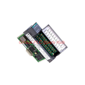
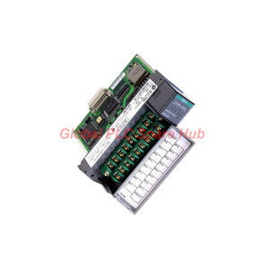
1746-NI8 SLC 500 Allen Bradley 8-Channel Analog Input Solution
Manufacturer: Allen-Bradley
Product No.: 1746-NI8
Condition: In stock
Product Type: Analog Input Module
Product Origin: USA
Payment: T/T, Western Union
Weight: 450g
Shipping port: Xiamen
Warranty: 12 months
Estimate delivery times: 12-26 days (International), 3-6 days (United States).
Return within 30 days of purchase. Duties & taxes are non-refundable.
Guaranteed Safe Checkout
Allen Bradley 1746-NI8 | Analog Input Engineering Profile
The 1746-NI8 is an eight-channel analog input module for the SLC 500 programmable controller platform from Allen Bradley.
It acquires voltage or current signals from compatible field instruments and transfers their converted values to the controller. Engineers can select supported signal ranges to match transmitters, sensors, and measurement circuits.
Its single-slot format supports compact I/O arrangements in existing SLC 500 installations. Class 1 and Class 3 configurations provide different input and output word allocations, subject to controller and configuration requirements.
01 | Product Identity and Configuration
| Identification | Details |
|---|---|
| Manufacturer | Allen Bradley |
| Model | 1746-NI8 |
| Product Family | SLC 500 |
| Module Category | Analog Input Module |
| Input Channels | 8 |
| Slot Occupancy | 1 slot |
| Input Configuration | High-impedance differential or single-ended inputs |
| Class Support | Class 1 and Class 3, subject to system configuration |
| UPC | 662072678039 |
| Listed Weight | Approximately 1.00 lb (0.45 kg) |
02 | Signal Selection Matrix
Choose the measurement range according to the field instrument output and the required engineering scale. Confirm the exact channel configuration in the applicable Allen Bradley manual.
| Signal Category | Supported Range | Typical Instrument Examples |
|---|---|---|
| Voltage | -10 to +10 V DC | Conditioning equipment, voltage-output transducers |
| Voltage | 0 to 10 V DC | Compatible position and process transmitters |
| Voltage | 0 to 5 V DC | Voltage-output measurement devices |
| Voltage | 1 to 5 V DC | Compatible conditioned process signals |
| Current | 0 to 20 mA | Current-output transmitters and signal conditioners |
| Current | 4 to 20 mA | Pressure, level, flow, and temperature transmitters with current outputs |
| Current | -20 to +20 mA | Compatible bipolar current-output devices |
| Current | 0 to 1 mA | Low-level current sources supported by the configured input range |
Selection rule: Match the instrument output, module range, and controller scaling. Never assume that every channel automatically detects its connected signal type.
03 | Class Configuration and Data Mapping
| Configuration | Output Words | Input Words | Engineering Consideration |
|---|---|---|---|
| Class 1 | 8 | 8 | Verify the required data layout and controller support. |
| Class 3 | 12 | 16 | Confirm the expanded data allocation and configuration requirements. |
Class selection affects the module's data organization and system configuration. Check the applicable hardware manual and processor compatibility before changing an existing installation.
04 | Engineering Benefits in Existing Control Systems
- Multi-signal support: Select compatible voltage or current ranges for different measurement instruments.
- Eight-channel acquisition: Consolidate multiple analog measurement points within one I/O slot.
- Flexible input wiring: Use supported differential or single-ended configurations according to the application.
- Visible input status: Use the module's indicators as one diagnostic reference during troubleshooting.
- Compact installation: Preserve rack space in compatible SLC 500 systems.
- Controller data access: Map acquired values into the control program for monitoring, alarms, calculations, and process interlocks.
05 | Equipment Compatibility and Typical Applications
This module suits applications that require analog measurement within a compatible SLC 500 control architecture. Confirm the controller, chassis, configuration, and electrical requirements before ordering.
| Equipment or Process | Potential Application | Pre-Installation Check |
|---|---|---|
| Process transmitters | Pressure, flow, and level monitoring | Confirm the current range and loop wiring. |
| Temperature instrumentation | Read conditioned temperature signals | Verify the transmitter's output type and scaling. |
| Hydraulic systems | Monitor pressure transducers and compatible sensors | Check signal conditioning and electrical noise. |
| Water treatment equipment | Acquire flow and pressure measurement signals | Verify signal ranges and controller data mapping. |
| Packaging machinery | Read analog feedback from compatible instruments | Confirm the required update behavior and control response. |
| Manufacturing lines | Collect process measurements for PLC logic | Review the existing rack configuration and spare-slot availability. |
Important: The module accepts supported voltage and current signals. It does not directly replace a thermocouple or RTD input module unless suitable external signal conditioning provides a compatible output.
06 | Installation and Commissioning Workflow
- Verify the rack: Confirm the SLC 500 chassis, processor, available slot, and hardware compatibility.
- Inspect the module: Check the product label, terminal condition, and physical connector.
- Plan the wiring: Identify signal polarity, common connections, shielding, and grounding requirements.
- Select the input range: Match the configured range to the connected instrument's output.
- Configure the controller: Set the correct module configuration and data mapping.
- Test individual channels: Apply a suitable reference signal and compare the result with the expected reading.
- Validate process scaling: Check the relationship between raw input values and engineering units.
- Document acceptance: Record channel assignments, test readings, alarms, and final configuration.
Follow site isolation procedures before installation or wiring changes. Use the manufacturer's instructions for terminal connections and electrical limits.
07 | Field Diagnostics: From Symptoms to Root Cause
| Observed Symptom | Recommended Investigation | Engineering Objective |
|---|---|---|
| Reading remains at zero | Check the field signal, wiring continuity, range selection, and channel mapping. | Separate wiring faults from configuration errors. |
| Reading fluctuates | Inspect grounding, shielding, nearby power cables, and instrument stability. | Identify interference or an unstable source signal. |
| Reading appears incorrect | Compare a reference input with the controller's raw and scaled values. | Locate scaling or range mismatches. |
| One channel differs from others | Test the field device and wiring independently, then compare channel configuration. | Isolate the problem to the field circuit or input channel. |
| Multiple channels fail together | Review shared wiring, common connections, module seating, and controller diagnostics. | Investigate common causes before replacing hardware. |
On-site example: A pressure transmitter reads correctly on a calibrator but shows an incorrect PLC value. Compare the configured current range, raw input data, and engineering-unit scaling. If the raw value matches the reference, investigate the control program before replacing the module.
Diagnostic limitation: Input indicators assist visual inspection, but they do not independently identify every wiring, scaling, or hardware fault. Use controller diagnostics and calibrated test equipment for confirmation.
08 | Global PLC Spare HUB Review
The 1746-NI8 is worth evaluating when an existing SLC 500 installation needs eight analog measurement channels and compatible voltage or current inputs.
For maintenance teams, the key selection factors are signal compatibility, channel configuration, controller support, and accurate program scaling. These checks help reduce avoidable commissioning delays.
During a replacement project, record the original channel assignments and representative process readings before removing the installed module. After installation, compare each channel against a known reference and verify the associated alarms and control logic.
For mixed-instrument applications, prepare a channel schedule before wiring. Record each instrument's output type, configured range, engineering units, and controller address. This simple document improves troubleshooting and simplifies future maintenance.
09 | Purchasing Checklist
- Confirm the complete catalog number: 1746-NI8.
- Verify the installed SLC 500 processor and chassis configuration.
- Confirm whether the application requires voltage or current measurement.
- Check the required input ranges and differential or single-ended wiring arrangement.
- Review Class 1 or Class 3 data configuration requirements.
- Confirm the required quantity, delivery destination, and expected installation date.
- Request technical verification if the existing module label or system documentation is incomplete.
10 | Packaging, Shipping, and Warranty
- Product: Allen Bradley 1746-NI8 analog input module.
- Packaging: Protective packaging suitable for electronic equipment; confirm the supplied accessories before ordering.
- Shipping Options: FedEx, UPS, or DHL, subject to destination and service availability.
- Dispatch Target: 24–48 hours after order acceptance and stock confirmation, where available.
- Warranty: 12 months under the agreed sales terms.
- Support: Contact our team for model verification, compatibility checks, and order assistance.
Delivery times depend on stock status, destination, customs procedures, and carrier schedules. Confirm dispatch timing before placing an urgent replacement order.
11 | Frequently Asked Questions
Q1: How should I choose between differential and single-ended input wiring?
Consider the instrument output, grounding arrangement, cable length, and electrical noise environment. Differential wiring can help reject common-mode interference when the installation meets the module's electrical requirements. Follow the manufacturer's wiring guidance for the selected configuration.
Q2: What should I check before replacing an installed analog input module?
Record the existing channel ranges, wiring assignments, raw input values, and controller scaling. Confirm the replacement model and rack compatibility. After installation, repeat representative signal tests before returning the process to normal operation.
Q3: Can this module read a thermocouple or RTD directly?
Do not assume direct support. The listed input types are voltage and current signals. Use a compatible signal conditioner or transmitter, and confirm that its output matches a supported module range.
Q4: How can I distinguish electrical noise from a scaling error?
Apply a stable reference signal and observe the raw controller value. Fluctuating raw values may indicate source instability, wiring problems, or interference. Stable raw values with incorrect engineering units point toward range selection or program scaling.
Q5: What information should I provide when requesting a replacement quote?
Provide the full catalog number, controller and chassis details, input signal types, required quantity, and destination. A clear module label photo and the existing channel configuration help suppliers verify compatibility and reduce ordering errors.
Request Pricing and Availability
Contact Global PLC Spare HUB to request a quotation for the Allen Bradley 1746-NI8 analog input module.
Share your application requirements and installed SLC 500 hardware details. Our team can review the requested configuration, check availability, and discuss suitable shipping options.
Tags
Q: Are these parts 100% original and new?
A: Yes. Every component is guaranteed to be 100% original, brand-new, and factory-sealed. We also provide a 12-month comprehensive warranty for your peace of mind.
Q: How fast is the shipping to my country?
A: For in-stock items, we offer same-day dispatch. International express shipping (DHL/FedEx/UPS) typically delivers within 3–5 business days worldwide.
Q: Can I get a formal quotation with shipping costs?
A: Absolutely. Our sales team is ready to provide a detailed Proforma Invoice (PI) including the most competitive shipping rates for your location.
Q: Do you offer discounts for bulk orders?
A: We provide volume-based pricing for large projects or multiple-item orders. Please contact us to get our Best Price Guarantee.
12-Month Comprehensive Warranty
Every part supplied by Global PLC Spare Hub is covered by a 12-month warranty from the date of invoice.
- Coverage: Functional defects and hardware failures under normal operating conditions.
- Commitment: We provide immediate repair, replacement, or a full refund for any verified defective components to minimize your operational downtime.
Returns & Exchange Policy
We offer a 30-day return policy to ensure you receive the exact part your system requires.
- Eligibility: Returns are accepted for uninstalled items in their original, factory-sealed packaging.
- RMA Process: Please contact our support team to obtain a Return Merchandise Authorization (RMA) number before shipping.
- Fast Processing: Refunds or exchanges are processed within 3–5 business days after the returned item passes our technical inspection.
Need Technical Assistance?Not sure if this part is compatible with your system? [Consult our Engineers] before purchasing to ensure 100% compatibility.
People Also Bought


