


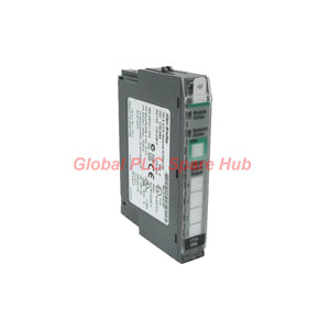
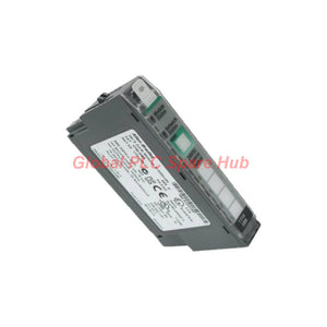

1734-OB8 Allen-Bradley 1734 POINT I/O Output Module
Manufacturer: Allen-Bradley
Product No.: 1734-OB8
Condition: In stock
Product Type: Output Module
Product Origin: USA
Payment: T/T, Western Union
Weight: 500g
Shipping port: Xiamen
Warranty: 12 months
Estimate delivery times: 12-26 days (International), 3-6 days (United States).
Return within 30 days of purchase. Duties & taxes are non-refundable.
Guaranteed Safe Checkout
Allen-Bradley 1734-OB8 | Eight-Point DC Output for Distributed Control
The Allen-Bradley 1734-OB8 is an eight-channel digital output module in the POINT I/O 1734 series. It provides discrete DC control signals for distributed automation architectures, allowing a controller to operate compatible field devices through a compact I/O platform.
For system integrators and maintenance engineers, selection should focus on more than the nominal 24V DC supply. Verify the load's operating current, channel grouping, total module current, inrush demand, and output behavior during controller startup or communication loss before commissioning.
01 | Output Capability at a Glance
| Parameter | Specification |
|---|---|
| Manufacturer | Allen-Bradley |
| Product family | POINT I/O 1734 series |
| Model | 1734-OB8 |
| Module type | 8-point DC digital output module |
| Nominal on-state voltage | 24V DC |
| On-state voltage range | 10–28.8V DC |
| Maximum on-state voltage drop | 0.2V DC (provided specification; confirm against the applicable manual) |
| Minimum on-state current | 1.0mA per channel (provided specification; confirm against the applicable manual) |
| Maximum off-state leakage | 0.5mA at 28.8V DC (provided specification; confirm against the applicable manual) |
| Output current rating | Provided data states 1.0A per output and 2.0A maximum; verify channel-group and module limits before use |
| Surge current | Provided data states 2A for 10ms, repeatable every 3 seconds; verify permitted conditions |
| Output signal delay | Provided data states a maximum of 0.1ms; verify the official timing specification |
| Indicators | 8 yellow output-status indicators and 2 green/red module/network indicators, as provided |
| Isolation voltage | Provided data states 50V continuous; verify the applicable isolation rating and test conditions |
| Listed weight | 0.31lb (approximately 0.14kg) |
| UPC | 10612598310279 (as provided; verify before catalog publication) |
02 | Load Matching: Check the Circuit Before Wiring
A digital output must match the electrical characteristics of its connected load. A nominal 24V DC rating alone does not establish compatibility with every relay, solenoid, indicator, or electronic input.
- Interposing relays: Check the relay coil's pickup current, steady-state current, and suppression requirements. Confirm that the output can switch the coil reliably without exceeding its permitted load.
- Solenoid valves: Evaluate coil inrush, continuous current, switching frequency, and inductive-energy suppression. Use a suitable interface device when the load exceeds the module's verified rating.
- Contactors: Confirm the coil's DC rating and switching characteristics. Do not assume that a contactor coil is compatible solely because its label specifies 24V DC.
- Signal lamps and electronic loads: Check startup current and minimum load requirements. Low-current loads may behave unexpectedly if their electrical characteristics interact with off-state leakage.
- PLC interface circuits: Verify the receiving device's input polarity, common reference, and voltage thresholds before connecting outputs to another controller or interface module.
Engineering note: Calculate the simultaneous load current under the intended operating condition. Keep the design within the module's verified channel, group, and overall current limits, including startup transients.
03 | Where the Module Fits in an Automation System
The 1734-OB8 can be considered for distributed control applications that require discrete DC switching. Final suitability depends on the complete POINT I/O assembly, controller architecture, power arrangement, wiring accessories, and load specifications.
| Equipment or application | Typical control task | Pre-installation check |
|---|---|---|
| Packaging machinery | Switching compatible indicators, relays, and discrete actuators | Confirm cycle frequency and simultaneous output demand |
| Conveyor systems | Controlling interface relays and selected DC control devices | Check startup sequences and output behavior during faults |
| Material-handling equipment | Operating compatible solenoid and relay circuits | Verify coil suppression and total current requirements |
| Process skids | Driving discrete control interfaces for auxiliary equipment | Review cabinet temperature, power quality, and grounding |
| Machine control panels | Switching pilot devices and downstream control interfaces | Confirm terminal accessories, wiring diagrams, and load polarity |
| Distributed I/O stations | Providing discrete outputs near field equipment | Verify network configuration and module compatibility |
This module should not be treated as a direct replacement for a safety-rated output or a dedicated motor power stage. Applications involving safety functions, large inductive loads, or high starting currents require the appropriate certified or rated interface equipment.
04 | Installation and Commissioning Sequence
- Confirm the assembly: Check the catalog number, POINT I/O adapter, mounting base, terminal arrangement, and installation documentation. Do not assume that a matching series number guarantees compatibility with every accessory.
- Isolate the power: Apply the site's lockout/tagout procedure and verify the absence of hazardous voltage before wiring or replacing the module.
- Inspect field wiring: Confirm the 24V DC supply, polarity, common connections, conductor condition, and terminal tightness against the applicable wiring diagram.
- Review load demand: Measure or obtain the load's steady-state and inrush current. Check the verified channel and group limits before connecting multiple loads.
- Validate controller configuration: Confirm the correct module identity, I/O mapping, controller program, and network configuration where applicable.
- Test outputs individually: Command each channel under controlled conditions. Compare the software command, indicator state, terminal voltage, and actual field-device response.
- Test abnormal conditions: Where the risk assessment permits, verify recovery behavior after a communication interruption, power cycle, or controller fault. Confirm the configured fault-state behavior rather than assuming outputs always turn off.
05 | Field Diagnostics: Separate Logic, Wiring, and Load Faults
When a field device does not respond, use a structured diagnostic sequence instead of replacing the output module immediately. The indicator state provides useful evidence, but it does not independently prove that the load circuit works correctly.
| Observed symptom | Possible cause | Recommended diagnostic action |
|---|---|---|
| Output command is ON, but the device remains inactive | Open field wiring, missing load supply, incorrect polarity, defective load, or an output-channel problem | Measure the output circuit under the actual load condition and inspect the wiring path |
| Output indicator remains OFF despite an ON command | Incorrect I/O mapping, controller logic conditions, configuration issues, or a module fault | Compare the controller tag, commanded state, module status, and configuration |
| Load activates intermittently | Loose terminals, unstable supply voltage, excessive inrush, or an intermittent field device | Inspect terminals and record supply voltage during switching; compare with load specifications |
| Load remains energized after the command turns OFF | Incorrect wiring, an external backfeed path, a failed output device, or load-specific behavior | Isolate the circuit safely and measure voltage with the load disconnected where appropriate |
| Multiple channels fail at the same time | Shared supply or common wiring problems, group-current overload, or a module-level issue | Check shared power distribution, common connections, load totals, and module diagnostics |
| Problems occur during startup or simultaneous switching | Transient current demand, supply dip, or a mismatch between actual and permitted load conditions | Measure startup current and supply voltage; compare the results with verified module limits |
Diagnostic caution: Follow the product manual's LED definitions and fault-handling instructions. Do not interpret an indicator color as a specific fault code without confirming its meaning for the installed hardware and firmware.
06 | Maintenance and Reliability Considerations
- Record the module catalog number and the connected load list in the cabinet documentation.
- Inspect terminals, conductors, and field-device connections during scheduled maintenance, following site isolation procedures.
- Review current demand after adding actuators or changing a machine sequence. A previously acceptable load group may exceed its limits after an upgrade.
- Investigate repeated channel failures by checking inductive suppression, short circuits, load inrush, and power quality before installing a replacement.
- Keep a verified spare available when unplanned downtime carries a high production cost. Confirm the complete assembly and configuration requirements before ordering.
07 | Global PLC Spare HUB's Insight
For maintenance teams, the key selection issue is not simply whether a module supports 24V DC. The more important question is whether its verified output limits match the actual field load and the installation's operating conditions.
Before purchasing the 1734-OB8, compare the existing module's full catalog number, installed POINT I/O hardware, wiring arrangement, controller configuration, and load requirements. If the module operates solenoid valves or relay coils, document both steady-state and startup current, along with the suppression method.
When diagnosing a suspected failure, compare the output command with the module indicator, terminal voltage, and field-device response. This approach helps distinguish controller logic issues from supply, wiring, load, and channel faults, reducing unnecessary component replacement.
Global PLC Spare HUB can help buyers review the requested model and clarify purchasing details. Confirm the exact catalog number, condition, availability, and delivery arrangements before placing an order.
08 | Ordering, Warranty, and Shipping
- Product: Allen-Bradley POINT I/O DC output module
- Model: 1734-OB8
- Warranty: 12-month warranty, subject to the seller's written warranty terms and coverage conditions
- Shipping options: FedEx, UPS, or DHL, subject to destination, service availability, and order arrangements
- Stock and lead time: Confirm current availability and dispatch timing when requesting a quotation
- Before ordering: Provide the full catalog number and any relevant photos or nameplate details to help verify the requested item
09 | Packaging and Supply Checklist
- 1734-OB8 output module, according to the confirmed order
- Packaging as specified in the quotation or order confirmation
- Applicable product identification and shipping documentation
Mounting bases, adapters, terminal accessories, cables, and other POINT I/O components should be confirmed separately. Do not assume that accessories are included unless the quotation explicitly lists them.
10 | Professional FAQs
Q1: What should I verify before replacing an installed 1734-OB8 with a spare?
Compare the full catalog number, installed base and adapter, wiring layout, controller configuration, and load requirements. During maintenance, record the existing wiring and configuration before removal. Confirm the replacement's compatibility against the applicable Rockwell Automation documentation rather than relying on appearance alone.
Q2: How can I tell whether a failed output channel or a field device causes the problem?
First confirm that the controller issues the intended command. Then compare the output indicator, supply voltage, terminal measurements, and field-device response. If the command and indicator agree but the load does not operate, inspect the field circuit and load. Perform electrical tests using approved procedures and appropriate instruments.
Q3: Is the module suitable for switching a 24V DC solenoid valve directly?
Not every 24V DC solenoid is a suitable direct load. Check the coil's steady-state current, inrush demand, inductive characteristics, switching frequency, and required suppression. Compare these values with the official module ratings and applicable channel-group limits. Use an appropriately rated interposing interface if the load exceeds those limits.
Q4: What information helps identify the correct spare when the original module label is damaged?
Collect clear photos of the remaining label, the POINT I/O station, the mounting base, terminal wiring, and the controller's module configuration. Record the adapter model and any available inventory records. Ask the supplier to verify the identification before ordering; do not select a replacement from the series name alone.
Q5: Which details should I include when requesting a quotation?
Provide the exact model number, required quantity, preferred condition, delivery country, and target delivery date. Include any compatibility questions, required documentation, and photos of the existing unit. Ask the supplier to confirm stock status, warranty terms, shipping options, and whether the quoted scope includes accessories.
Request a quotation for the Allen-Bradley 1734-OB8. Share your required quantity, delivery destination, and existing hardware details to help confirm the correct item and shipping arrangement.
Tags
Q: Are these parts 100% original and new?
A: Yes. Every component is guaranteed to be 100% original, brand-new, and factory-sealed. We also provide a 12-month comprehensive warranty for your peace of mind.
Q: How fast is the shipping to my country?
A: For in-stock items, we offer same-day dispatch. International express shipping (DHL/FedEx/UPS) typically delivers within 3–5 business days worldwide.
Q: Can I get a formal quotation with shipping costs?
A: Absolutely. Our sales team is ready to provide a detailed Proforma Invoice (PI) including the most competitive shipping rates for your location.
Q: Do you offer discounts for bulk orders?
A: We provide volume-based pricing for large projects or multiple-item orders. Please contact us to get our Best Price Guarantee.
12-Month Comprehensive Warranty
Every part supplied by Global PLC Spare Hub is covered by a 12-month warranty from the date of invoice.
- Coverage: Functional defects and hardware failures under normal operating conditions.
- Commitment: We provide immediate repair, replacement, or a full refund for any verified defective components to minimize your operational downtime.
Returns & Exchange Policy
We offer a 30-day return policy to ensure you receive the exact part your system requires.
- Eligibility: Returns are accepted for uninstalled items in their original, factory-sealed packaging.
- RMA Process: Please contact our support team to obtain a Return Merchandise Authorization (RMA) number before shipping.
- Fast Processing: Refunds or exchanges are processed within 3–5 business days after the returned item passes our technical inspection.
Need Technical Assistance?Not sure if this part is compatible with your system? [Consult our Engineers] before purchasing to ensure 100% compatibility.
People Also Bought


