


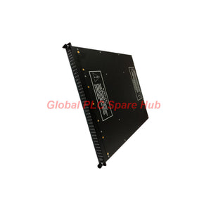
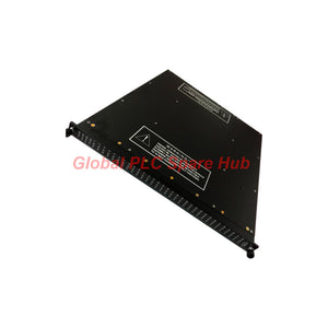
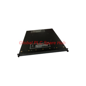
3625A Triconex Digital Output Module | TMR Control Solution
Manufacturer: Triconex
Product No.: 3625A
Condition: متوفر بالمخزون
Product Type: Digital Output Module
Product Origin: USA
Payment: T/T, Western Union
Weight: 5500g
Shipping port: Xiamen
Warranty: 12 months
تقدير أوقات التسليم: 12-26 يومًا (دوليًا)، 3-6 أيام (الولايات المتحدة).
يجب الإرجاع خلال 30 يومًا من الشراء. الرسوم والضرائب غير قابلة للاسترداد.
دفع آمن ومضمون
Product Brief | Safety-Critical Digital Output Control
Triconex 3625A is specified here as a 32-point digital output module for Tricon safety and industrial control applications. It provides commoned DC output channels, configurable point supervision, and diagnostic status indications.
The module uses a Triple Modular Redundant (TMR) architecture with voted output circuitry, according to the supplied specifications. This architecture supports fault-tolerant operation within a correctly configured Tricon system. Actual safety performance depends on the complete system design, approved hardware configuration, application logic, and validation process.
Designed for nominal 24 V DC operation, the 3625A supports a recommended supply range of 16–32 V DC and a stated maximum voltage of 36 V DC. Its 32 output points can be configured for supervised or non-supervised operation, subject to the installed system configuration.
Engineering Data | Electrical and Diagnostic Specifications
| Parameter | Specification |
|---|---|
| Manufacturer / Brand | Triconex / Invensys |
| Model | 3625A |
| Product Type | 32-point digital output module |
| System Family | Tricon safety and control system; verify exact revision compatibility |
| Output Configuration | 32 commoned output points |
| Output Supervision | Supervised or non-supervised; configurable per point where supported |
| Nominal Operating Voltage | 24 V DC |
| Recommended Voltage Range | 16–32 V DC |
| Maximum Voltage | 36 V DC |
| Maximum Point Current | 1.70 A ±10% per point, as specified |
| Surge Current | Source specifications conflict; verify the applicable hardware manual before design |
| Total Output Current | 10 A per termination panel |
| Minimum Required Load | 10 mA |
| Output Leakage Current | 2.0 mA at 24 V DC; 2.5 mA at 32 V DC |
| Logic Power | Less than 13 W |
| System-to-Field Isolation | 1,500 V DC minimum |
| Short/Open Circuit Detection | Programmable threshold for supervised points |
| Maximum Output Toggle Rate for Diagnostic Fault Coverage | One toggle every 60 ms, according to supplied data |
| Diagnostic Glitch Duration | 2 ms maximum; 200 μs typical |
| Output Protection | Self-protection against overvoltage, overtemperature, and overcurrent, as specified |
| Inductive Load Protection | Self-protected output switches against reverse EMF, as specified |
| Field Termination Fuses | Not required according to the supplied specifications; verify installation requirements |
| Color Code | Dark blue |
| Operating Temperature | −40 to +70°C, or up to +85°C depending on revision; verify exact hardware revision |
Output Performance | Current, Leakage and Voltage Drop
Output selection requires more than checking the nominal supply voltage. Engineers must evaluate the load current, shared termination-panel limit, OFF-state leakage, and voltage drop across the output path.
| Output Path | Load Condition | Typical Voltage Drop |
|---|---|---|
| At backplane | 250 mA | Less than 0.16 V DC |
| At backplane | 1.7 A | Less than 1.12 V DC |
| External termination with 10 ft cable | 250 mA | Less than 1.15 V DC |
| External termination with 10 ft cable | 1.7 A | Less than 3.33 V DC |
| External termination with 99 ft cable | 250 mA | Less than 2.71 V DC |
| External termination with 99 ft cable | 1.7 A | Less than 8.92 V DC |
Engineering implication: Longer field wiring can significantly reduce the voltage available at the load. Calculate the load's minimum operating voltage using the supply voltage, output-path voltage drop, and cable characteristics before commissioning.
Current budget: The specified 1.7 A maximum per point does not override the 10 A total limit per termination panel. Check individual channel current and aggregate panel current independently.
Leakage consideration: The specified OFF-state leakage reaches 2.0 mA at 24 V DC and 2.5 mA at 32 V DC. Confirm that the connected device will reliably turn OFF at these leakage levels, especially when using sensitive electronic loads.
TMR Architecture | What Engineers Should Verify
- Redundant processing: Confirm that the module operates within the intended Tricon TMR system architecture.
- Output configuration: Verify whether each point requires supervised or non-supervised operation.
- Load distribution: Calculate channel current and the combined termination-panel current.
- Fault monitoring: Confirm configured short-circuit and open-circuit detection thresholds for supervised points.
- Diagnostic timing: Check the application against the stated output-toggle and diagnostic-glitch characteristics.
- Revision control: Verify temperature limits, surge ratings, and system compatibility for the exact hardware revision.
The TMR designation alone does not establish that every field load or external circuit is redundant. Verify the full safety loop, termination hardware, wiring, and application design before relying on the system for a safety function.
Suitable Equipment and Application Scenarios
- Tricon safety systems: Digital output control within a verified compatible Tricon installation.
- Industrial shutdown applications: Command compatible field devices as part of a properly engineered safety instrumented function.
- Process plant control: Switch eligible DC field loads associated with configured process control or protection logic.
- Valve and actuator interfaces: Control compatible solenoids or interface devices after checking load current, inductive characteristics, and termination limits.
- Alarm and interlock circuits: Operate configured DC output circuits where the load requirements match the module's electrical characteristics.
- Maintenance replacement: Replace a matching installed module after verifying hardware revision, system configuration, and termination compatibility.
These examples describe potential applications based on the supplied specifications. Confirm the specific Tricon controller version, termination panel, field wiring, and load requirements before selecting the module.
Global PLC Spare HUB's Insight | Fault Isolation Workflow
Scenario 1 — Output command is active, but the field load does not energize. Verify the field supply voltage and measure voltage at the load under operating conditions. Check the termination-panel current budget, cable resistance, terminal connections, and load continuity before concluding that the output channel has failed.
Scenario 2 — A load remains partially energized after the output turns OFF. Measure the OFF-state voltage and assess the load's sensitivity to leakage current. Compare the result with the specified leakage values and inspect external wiring for unintended backfeed paths.
Scenario 3 — Several outputs fail under simultaneous operation. Calculate the total current for the termination panel and compare it with the 10 A limit. Check supply stability, shared wiring, and load inrush characteristics. Do not diagnose each channel independently until common-circuit causes have been excluded.
Scenario 4 — A supervised point reports an open- or short-circuit fault. Inspect the field cable, load continuity, terminal connections, and configured detection threshold. Verify that the selected supervision mode matches the intended field circuit and system configuration.
Scenario 5 — Intermittent faults appear with long field cables. Measure voltage at both the termination point and the connected load. Compare the observed voltage drop with the expected cable and output-path behavior. Review the cable length and load current before replacing the module.
Scenario 6 — Fault behavior differs after module replacement. Verify the complete model number, hardware revision, system version, supervision settings, and termination hardware. Temperature specifications and surge-current details should be checked against the applicable revision documentation.
Recommended diagnostic record: Record the output point, commanded state, measured field voltage, load current, termination-panel total current, cable length, supervision configuration, module indicators, and hardware revision. This provides a repeatable basis for distinguishing load, wiring, configuration, and module-related faults.
Installation and Commissioning Checklist
- Confirm the module identity: Verify the 3625A part number and revision against the installed system documentation.
- Check system compatibility: Confirm the Tricon system version and supported termination hardware. Do not rely solely on a general compatibility statement.
- Verify power conditions: Confirm the DC supply remains within the approved range for the applicable revision.
- Calculate load current: Check the maximum current for each point and the total current per termination panel.
- Assess cable voltage drop: Include field cable length, output-path drop, and the load's minimum operating voltage.
- Review supervision: Verify per-point supervision settings and detection thresholds where applicable.
- Check output protection: Confirm the connected load is compatible with the module's switching and protection characteristics.
- Perform approved functional tests: Validate output behavior and diagnostics using the plant's authorized maintenance and safety procedures.
- Document results: Record configuration, measurements, test results, and the final system status before return to service.
Frequently Asked Questions
Q1: How do I assess whether a field load is suitable for this output module?
A: Check the load's nominal voltage, steady-state current, inrush current, minimum operating voltage, and behavior during OFF-state leakage. Then calculate the total termination-panel current and the expected voltage drop at the actual cable length.
Q2: Why might a load fail even when its current is below the per-point limit?
A: The shared termination-panel limit, cable voltage drop, load inrush, and supply stability can still prevent reliable operation. Evaluate the entire output circuit rather than treating the individual channel rating as the only selection criterion.
Q3: What information should I provide when sourcing a replacement 3625A?
A: Provide the complete part number, hardware revision, Tricon system version, termination-panel model, required quantity, and field application details. A photograph of the module label and existing installation can help identify configuration differences.
Q4: Can I use the stated temperature range and surge rating for every 3625A revision?
A: No. The supplied data lists different upper temperature limits and conflicting surge-current descriptions. Verify the exact hardware revision and its official specification before finalizing environmental qualification or load design.
Q5: Does the SIL 3 capability of the module automatically make the entire application SIL 3 compliant?
A: No. SIL capability is not a blanket certification of the complete installation. The safety function must be assessed and validated as a whole, including the controller, application logic, field devices, wiring, diagnostics, configuration, and applicable safety documentation.
Warranty, Packaging and Shipping
- Product: Triconex 3625A 32-point digital output module.
- Warranty: 12-month warranty, subject to the supplier's applicable warranty terms.
- Shipping Methods: FedEx, UPS, and DHL, subject to destination and service availability.
- Order Verification: Confirm the model, hardware revision, system version, and termination-panel compatibility before ordering.
- Packaging: Protective packaging suitable for electronic industrial control components. Confirm special handling requirements when requesting a quotation.
Request a Quote: Contact Global PLC Spare HUB for 3625A pricing, availability, shipping options, and assistance verifying replacement compatibility.
Safety Notice: This module may be used in safety-related applications. Replacement, configuration, and functional testing must follow approved site procedures and applicable Tricon documentation. Qualified personnel must verify the complete safety function before the system returns to service.

Tags
س: هل هذه الأجزاء أصلية وجديدة 100%؟
ج: نعم. نضمن أن كل مكون هو أصلي 100%، وجديد تمامًا، ومغلف من المصنع. كما نقدم ضمانًا شاملاً لمدة 12 شهرًا لراحتك.
س: ما مدى سرعة الشحن إلى بلدي؟
ج: بالنسبة للعناصر المتوفرة في المخزون، نقدم إرسالاً في نفس اليوم. وعادةً ما يتم التسليم عبر الشحن السريع الدولي (DHL/FedEx/UPS) في غضون 3-5 أيام عمل في جميع أنحاء العالم.
س: هل يمكنني الحصول على عرض أسعار رسمي يشمل تكاليف الشحن؟
ج: بالتأكيد. فريق المبيعات لدينا مستعد لتقديم فاتورة مبدئية (PI) مفصلة تتضمن أسعار الشحن الأكثر تنافسية لموقعك.
س: هل تقدمون خصومات للطلبات الكبيرة؟
ج: نقدم أسعارًا تعتمد على الحجم للمشاريع الكبيرة أو طلبات العناصر المتعددة. يرجى الاتصال بنا للحصول على ضمان أفضل الأسعار لدينا.
ضمان شامل لمدة 12 شهرًا
كل جزء توفره Global PLC Spare Hub مشمول بـ ضمان لمدة 12 شهرًا من تاريخ الفاتورة.
- التغطية: عيوب وظيفية وأعطال في الأجهزة في ظل ظروف التشغيل العادية.
- التزامنا: نقدم إصلاحًا فوريًا أو استبدالًا أو استردادًا كاملاً لأي مكونات معيبة تم التحقق منها لتقليل وقت التوقف التشغيلي لديك.
سياسة الإرجاع والاستبدال
نقدم سياسة إرجاع لمدة 30 يومًا لضمان حصولك على الجزء الدقيق الذي يتطلبه نظامك.
- الأهلية: تُقبل المرتجعات للعناصر غير المركبة في تغليفها الأصلي والمحكم الإغلاق من المصنع.
- عملية RMA: يرجى الاتصال بفريق الدعم لدينا للحصول على رقم ترخيص إرجاع البضائع (RMA) قبل الشحن.
- معالجة سريعة: تتم معالجة المبالغ المستردة أو الاستبدالات في غضون 3-5 أيام عمل بعد أن يجتاز العنصر المرتجع فحصنا الفني.
هل تحتاج إلى مساعدة فنية؟لست متأكدًا مما إذا كان هذا الجزء متوافقًا مع نظامك؟ [استشر مهندسينا] قبل الشراء لضمان التوافق بنسبة 100%.
اشترى الناس أيضًا


